


Years ago I tried making LED shorts for someone I was dating (Another Link) and quickly ran into how hard it is to merge fabric and electronics. Fabric is flexible, washable, and built to move. Electronics are rigid, fragile, and not made for that world. I started experimenting with ways to integrate circuits into textiles.
After many many experiments, I found conductive thread could be used to sew functional traces. But nobody had pushed that idea into real, complex circuits. I set out to see if you could reliably embroider working circuits with conductive thread and sewn-in components. In the beginning I started out with LED strips like everyone else, but they had severe limitations. I then moved to LED sequins as I saw on Adafruit but had no success with them, The problem with ALL readily available sewable components is that their geometry is not optimized for sewing. It was very difficult to get reliability from anything on the market so I developed my own LED sequins and iterated until I found something that worked. The following image shows the progression from soldered strips to machine sewn.
There were no tools for this. No software. No best practices. No hardware to reverse engineer. I took a leap and bought an industrial embroidery and designed a full set of sewable PCBs. At this time I had never embroidered and did not know if my ideas were possible with the machine. Through constant iteration I figured out what worked, what failed, and what circuit geometries gave the best results.
Standard Embroidery Software was great for graphics but terrible for circuits. Existing tools didn’t treat sewn traces like circuits and had no awareness of layout rules or electrical behavior. Standard SW also had no knowledge of component placement or how to avoid crashes. Here I was, crashing my machine and spending more time fixing it than I spent designing.
The crash in this image came from a single misplaced stich out of 130, 000
After 2 years of consistent "failure" I was too far invested to quit. I locked myself away and got to writing a custom CAD software that took in mind all of the lessons I had learned through trial and error. I needed to be certain that when I press go I could walk away from the machine. This software, that I call Digital Fiber Studio integrates the boards I have designed as drag and drop components and has shortcuts for various circuit techniques and ensures the design does not have machine crashing errors. It also has a simulator so that you may track the needle path before running pattern on the machine.
Stitch Simulator
Understanding the GloveFlex Sensors
There have been many iterations of a flex glove in the past. They typically use resistive flex sensors in a voltage divider circuit. Each sensor is paired with a fixed resistor and when the sensor bends its resistance changes which in turn changes the voltage between the sensor and the resistor. This voltage is then read by a micro controller and some action can be taken. The image shows this circuit layout. A quick google search will return many of these.
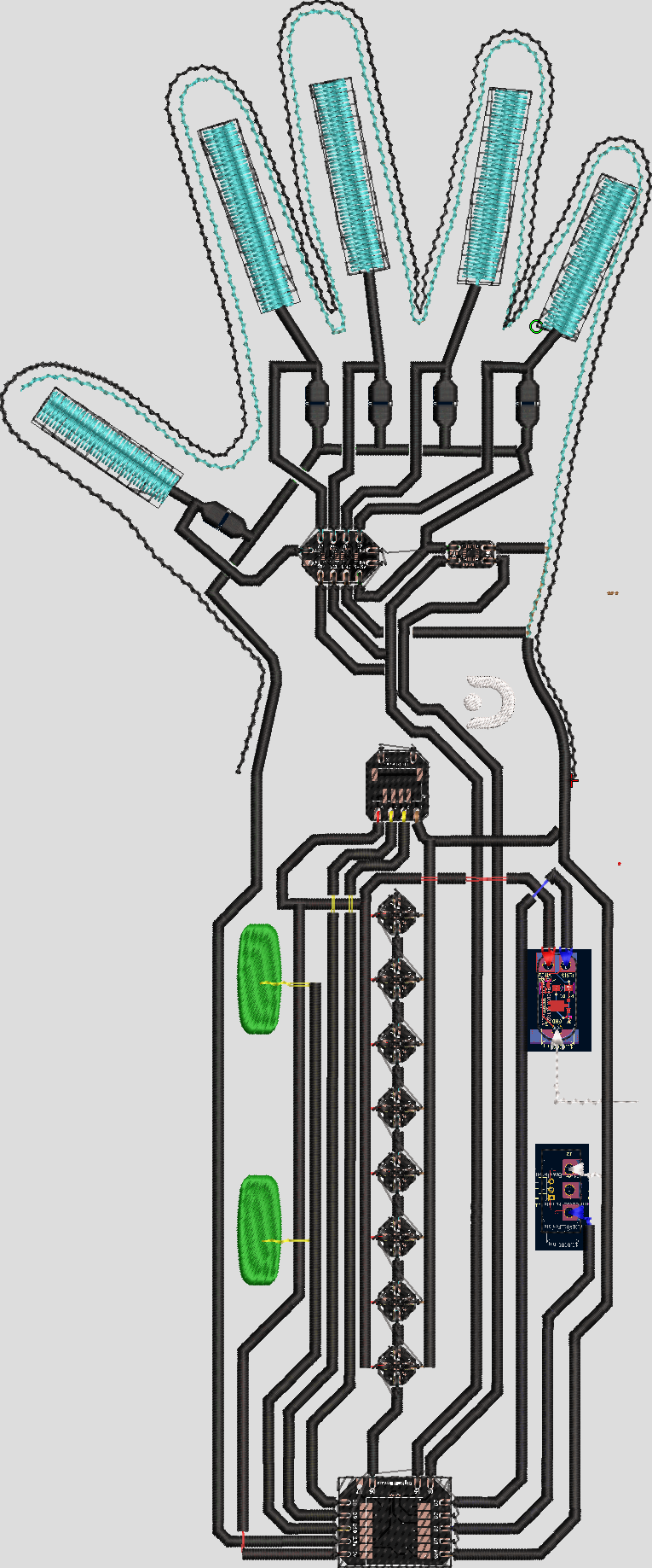
For this glove, the flex sensors are made up of conductive thread. The rectangular form on each finger is a textile flex sensor. If you look closely you'll see it tie into a resistor and the ADC. They integrate well into the fabric and are washable and comfortable
IMU
For Orientation, I use the common MPU6050 in sewable form. I wanted to use as many maker friendly parts as possible to simplify software for other engineers. It has an accelerometer, a gyro, and a temp sensor.
ADC
To read the analog signals generated by the voltage divider network an 8Pos ADC is used. Both it, and the IMU hang on the same I2C bus.
LEDs
For visual Feedback there are (8) ws2812-2020 LEDs on a tiny sequin
Buzzer and Vibrating Motor
A buzzer and vibrating motor are also included for user feedback
There are 23 steps to this design. For the sake of brevity I will cover the most relevant steps. The others have to with operating the machine and that's another story
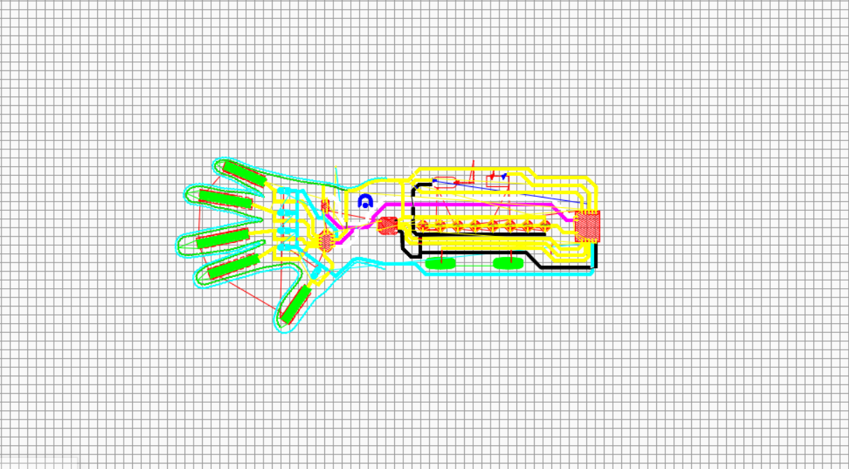
Study this layout. Each of the components are integrated as drag and drop. When a trace connects to a pin, the SW ensures the needle will not hit a component due to design error
1. SDA and SCL are routed from the MCU to the ADC and IMU
2. Ground is routed around the perimeter of the glove to give easy access to all components. All components are tied into ground. Bridges are used for crossing traces
3. The flex sensors are created and they tie into the fixed resistors and the ADC
4. 3.3v is routed from the MCU up to the ADC, Resistors, and MPU6050. I did not add voltage regulators due to size constraints. This forces me to use both 3.3v and 5v traces
5. 5v is routed to the LEDs and to the 4 pin generic connector used for the Ultrasonic sensor, or whatever else.
6. Data lines for the LEDs are routed and tied into the MCU
7. PWM signals are routed to the buzzer and the vibrating motor
8. (2) GPIO pins are routed to the generic 4 pin connector. The capacitive touch sensors are tied into the MCU
There are many new techniques at play that are not done in traditional electronics. For example, sequencing. It is important that the manufacturing phase follow a specific order. For example, you would want your bridges to come after the trace they're protecting, but maybe not directly after. Thread changes take time and should happen where they make sense. Another new thing is tie-in and tie-out. You must strategize where the needle jumps in and out of the circuit to avoid short circuits. Hard to find shorts are probably the toughest part of e-textiles. I've thrown projects away due to not being able to find the one tiny strand that shorts.
A closer look at why tie ins and tie outs are important in embroidered circuits.
Digital Fiber Studio automates tie ins
Yes - Mostly
I damaged a resistor so there are issues with one of the Flex sensors but overall it worked well as a proof of concept. It would take more engineering to really dial it in but this demonstrates that it is possible.
Conclusion
E-Textiles are still in the infant phase. To get us out of it we need more engineers involved. I hope this project inspires others to experiment with e-textile circuits.


Comments