


Hardware components | ||||||
 |
| × | 1 | |||
| × | 1 | ||||
| × | 2 | ||||
| × | 1 | ||||
| × | 1 | ||||
| × | 1 | ||||
 |
| × | 1 | |||
 |
| × | 2 | |||
 |
| × | 2 | |||
 |
| × | 1 | |||
Software apps and online services | ||||||
 |
| |||||
Hand tools and fabrication machines | ||||||
 |
| |||||
This project was made as the final project for ECEN 2440, Applications of Embedded Systems at the University of Colorado Boulder. We were inspired to make a CNC pen which would draw images. However, due to the time constraints of the project we decided to instead control the pen with a joystick. For the class we needed to use the MSP432 for the project.
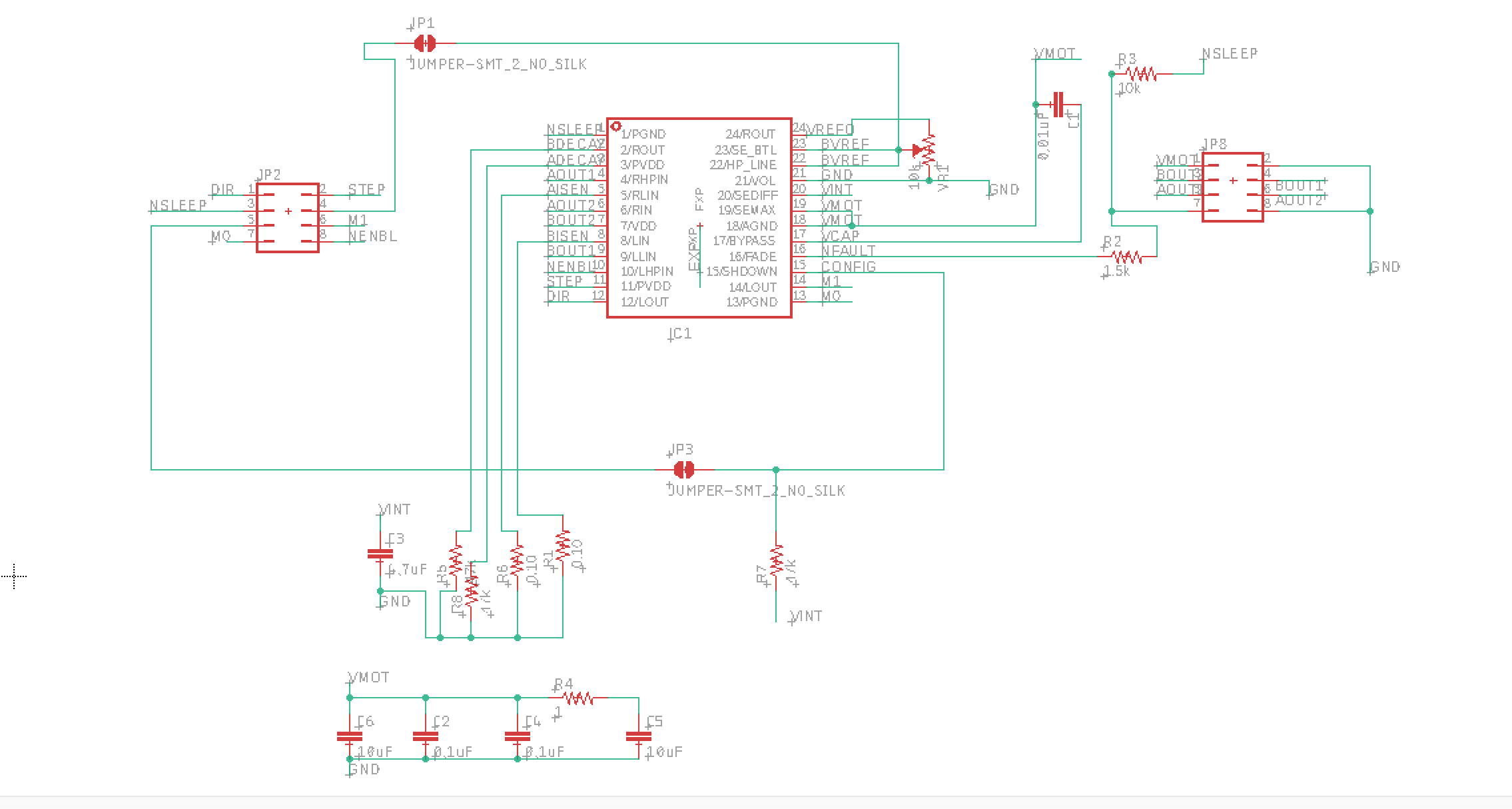
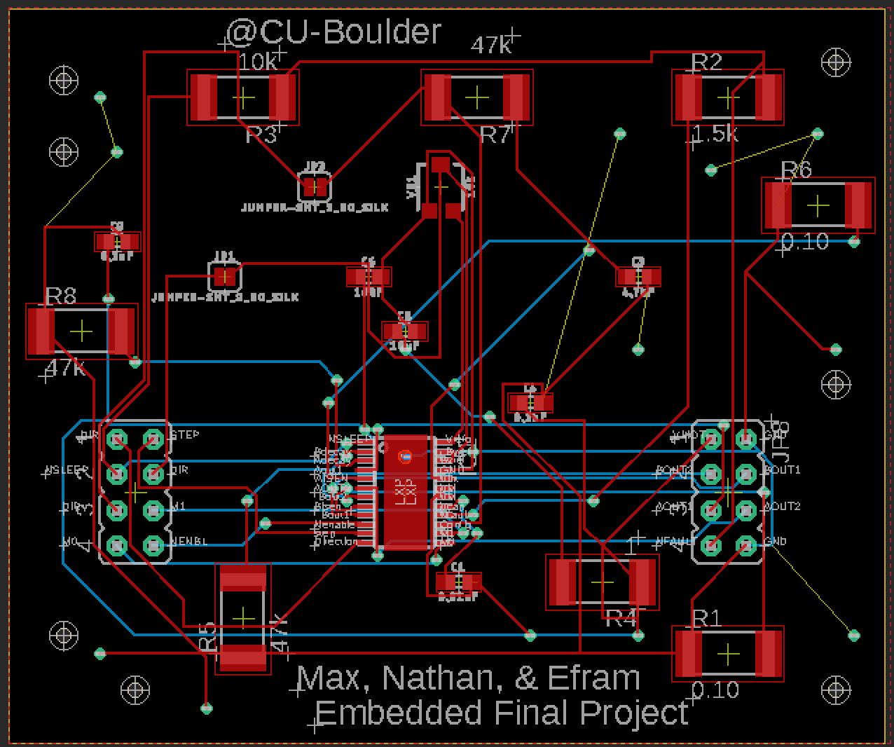
We also made our own stepper motor driver boards. Inspired by examples on Pololu.com we built a PCB for the DRV8834 to control our stepper motors.
In the end, we ended up only being able to draw in one dimension. Both motors worked and could be controlled with the joystick, but, unfortunately, at some point when we began to combine all of the components we burnt out the top motor. Possibly due to wiring it up incorrectly during reconstruction because, as you can see, we have a spaghetti knot of wires.
Should we build upon this project we would like to get the second motor working, replace the wiring mess with a custom shield, and reinforce the motors to make them more stable.
How it WorksControllingtheMotors:
The joystick's position is interpreted by the MSP's analog to digital converter. This position then triggers a PWM signal and direction to be sent to the motor drivers. The motor drivers, once configured, will rotate their motor one step on each rising edge of the PWM input, the direction of rotation depends on if the direction pin is high or low. Each dimension (left/right and forward/backward) uses their own timer and PWM signal and their own driver board.
MovingthePenHeight:
A servo lifts and lowers the pen. The position of the servo depends on the duty cycle of input PWM signal with a 20ms period. The clicking of the pen causes the select pin on the joystick to short to ground. An input pin of the MSP is between pull-up resistors and the select pin of the joystick. When the button is clicked a falling edge interrupt occurs on the input pin to the MSP. This interrupt then toggles the pen height by changing the duty cycle.
LCDScreen:
The MSP uses serial, UART, communication to print messages on the LCD display. An eUSCI (Enhanced Universal Serial Communication Interface) on the MSP was used for this. Once it is configured, strings can be loaded into the TX buffer and printed on the display. Each time the pen height is toggled, the new position is printed on the display.
The screen is sort of an homage to the inspiration of a CNC pen, should the pen draw from computer images, the display could show the printing progress or status.
Pin MapEach motor driver could share the configuring pins (Enable, Config, nSleep, M0, and M1) but we separated them in order troubleshoot the motor failure.
PrototypingThis project involved more mechanical needs than three electrical engineering students anticipated. One such need was for a mechanism to raise and lower the pen without affecting is location in combination with the ability to reload pens while staying light enough to not stress the motors.
The final design utilizes a clip ripped from a cheap compass and protractor set to hold the pen and paper clips as lever arms so that the clip can slide in and out if adjustments are needed.
We went through 2 MSP432 launchpads because we were powering the servo from the MSP directly to begin. We ended up drawing too much power and as a result the MSP would overheat to the point of burning you even while idle. So we quickly got another board and a LM7805 IC in order to use a 9V battery to power the servo.
Neither motor would rotate at first, before testing we had significantly lowered the frequency of the input signal fearing the motor would rotate too quickly and hit the screws edge. The frequency was then too low for anything to happen.
At first, the only things that would appear on the LCD screen when trying to write to it were X's and squares. This made it clear that we were sending something out but that something was off. Testing proved that we were at the wrong baud rate.
We recognized too late that having 40+ wires was not a good idea. Many problems came from wires getting disconnected or when we would move the project and have to reconstruct it. Many other projects from our class used a custom PCB to avoid this but we wanted the challenge of building our own motor drivers and did not have the time to do 2 custom PCBs.
A Saleae logic analyzer was used to test the UART output. This allowed us to see that we were configured for the wrong baud rate and needed to work through the equations MSP's technical reference manual.
Once the upper motor stopped working we walked through many tests to determine what could be the cause:
- Disconnected everything else from power
- Swapped the motor driver with the known working driver
- Raised and lowered the frequency of the PWM signal
- Raised and lowered the step size (by changing M0 and M1 pins on driver board to high or low)
- Using an Arduino to control it
None of these caused the motor to rotate, though some caused the motor to squeal and get very hot.
Oscilloscopes and multimeters were also fundamental in testing. Oscilloscopes were especially useful for visualizing PWM waves and measuring frequencies and duty cycles.
NotesA Voltera PCB Printer was used to apply the solder paste on our PCB and then a reflow oven was used.
Due to time constraints the button on the joystick was not debounced, hence the stuttering in the video.
Code was modified after the motor lost functionality and would need to be adjusted back before running it with 2 stepper motors.


_3u05Tpwasz.png?auto=compress%2Cformat&w=40&h=40&fit=fillmax&bg=fff&dpr=2)

Comments