

In this tutorial, we will build an IoT-based smart helmet equipped with multiple safety and monitoring features. We'll accomplish all that using easily available components.
You don't require advanced engineering expertise or complex components to make this work. It's a relatively simple Arduino project.
The project works in two parts:1. Transmitter - goes inside the helmet2. Receiver - is installed in the vehicle
Core Features of the Smart HelmetHere are the four core features that we’ll integrate into this project:
1. Theft detection
2. Wear detection
3. Alcohol detection
4. Drowsiness detection
Assembly of Transmitter Section (Helmet)1. Fix the Arduino inside the helmet well enough so it stays in place.
2. Connect the MQ3 alcohol sensor close to the rider’s mouth to analog input A0, and fix the IR eye blink sensor inside the helmet facing the rider’s eyes on digital pin D2.
3. Place the IR proximity sensor to check if the helmet is being worn on digital pin D3, and install the theft detection push button inside the helmet on digital pin D4.
4. Connect the 433 MHz RF transmitter module (data pin to D12) and position the antenna to get a good signal.
5. Power the system safely with a 9V or Li-ion battery inside the helmet, and make sure that the wiring are neat to prevent anything from coming loose.
Note: Refer to the schematic section for detailed wiring connections.
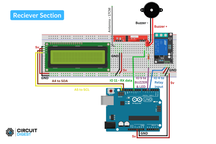
1. Fix the Arduino inside the vehicle near the ignition area.
2. Connect the 433 MHz RF receiver module (data pin to D11) and place the antenna where it can pick up signals best.
3. Attach the buzzer on pin D5 and the relay module on pin D6 to handle ignition.
4. Connect the 16x2 LCD display via I2C (A4 for SDA, A5 for SCL) and mount it someplace visible on the dashboard.
5. Power the setup from the vehicle’s 5V supply and try to keep the wiring clean to make sure everything is safe near the ignition.
Note: Refer to the schematic section for detailed wiring connections.
The Smart Helmet transmitter’s loop() constantly reads sensor pins to check whether the helmet is being worn, if alcohol is detected, or if the rider is drowsy. It uses a for loop to check timestamps in a circular buffer to detect drowsiness within a time window. If drowsiness is detected (isDrowsy), the buzzer is activated. Every 50 ms, sensor states are formatted into a comma-separated string, converted to a char array, and sent via rf_driver.send().
The receiver’s loop() listens for RF data, parses the received string into helmet, alcohol, and sleep statuses, and controls the ignition relay accordingly, only allowing the engine if the helmet is worn and no alcohol is detected. It triggers the buzzer for unsafe conditions and displays status pages on the LCD, switching every 3 seconds. If no data arrives for 5 seconds, it shows “System Offline” and sounds the buzzer.
This system enforces helmet use, detects drowsiness and intoxication, alerts the rider, and disables the vehicle ignition when unsafe. The full code is available in the code section.
WorkingTheft detection gets activated when the receiver stops getting signals from the helmet, obviously indicating it has been moved away. This triggers an alert buzzer and warning light. Wear detection works using an IR sensor that detects if the helmet is actually being worn. When the helmet is on, the system enables the vehicle’s ignition and updates the display accordingly. For drowsiness detection, the system monitors eye blinking patterns and sounds an alert if the eyes remain closed for a while. Alcohol detection is done using the MQ3 sensor. If alcohol is detected, the vehicle ignition is disabled until the sensor clears.
For reliable performance, it’s vital that we properly adjust the sensor thresholds and carefully position all sensors.
ConclusionIn short, this IoT project turns a regular everyday helmet into a smart helmet that's so simple that almost anyone can build it. A combination of theft alerts, wear detection, drowsiness monitoring, and alcohol sensing gets you real-time protection and control over vehicle ignition.


Comments