


Hardware components | ||||||
 |
| × | 1 | |||
 |
| × | 1 | |||
 |
| × | 1 | |||
 |
| × | 1 | |||
 |
| × | 1 | |||
Software apps and online services | ||||||
 |
| |||||
| ||||||
We have already seen how to send and receive data through the HC-05 but most blue tooth applications require more than just sending and receiving. In this tutorial, we will see how to interface the HC-05 with a 0.91 in. OLED display to print the data that the HC-05 receives.
SoftwareTo send the data, we will use The Arduino Bluetooth Controller (click here to download).
Note: The HC-05 Bluetooth Module only works on Android Devices.Hardware
HC-05 Bluetooth Module
- Bluetooth Version: The HC-05 module supports Bluetooth version 2.0+EDR (Enhanced Data Rate), providing a relatively stable and reliable connection.
- Serial Communication: The module uses a serial communication interface to communicate with the Arduino. It connects to the Arduino board using the UART pins, labeled as RX (receive) and TX (transmit).
- Operating Modes: The module has two primary operating modes: Command Mode (AT Mode) and Data Mode (Receiving and Sending data). In AT Mode, you can send configuration commands to the module, specifying parameters such as the Bluetooth name, PIN code, and operating mode. In Data Mode, you can send and receive data.
- Power Supply: The HC-05 module requires a power supply of around 3.3V. However, it is usually tolerant of 5V logic levels, making it compatible with most Arduino boards.
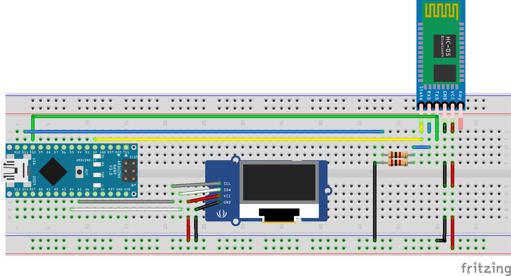
Note: If we look at the schematic, we can see that the HC-05 module's key pin is attached to VCC of the Arduino nano. The key pin should be attached to VCC before powering up the Arduino and must be disconnected once the HC-05 module starts to blink slowly.
Though we are using the HC-05 Bluetooth module for this project which is very cheap and durable, we use a voltage divider circuit to make sure that the RXD pin doesn't get damaged. It is made by attaching a 1k Ω potentiometer across RXD and Pin 11 and a 2k Ω potentiometer across RXD and Ground.
OLED Display:
- Compact Size: Ideal for small devices like smartwatches and fitness trackers due to its compact size.
- High Contrast and Brightness: Offers deep blacks and vibrant colors with high contrast and brightness.
- Low Power Consumption: Consumes less power than LCDs, enhancing battery life in wearable devices.
- Wide Viewing Angles: Maintains consistent color and clarity from various viewing angles.
- Fast Response Time: Provides rapid response times, reducing motion blur for dynamic content.
OLED displays are found in a wide range of devices, from smartphones and TVs to wearables and digital signage, due to their superior image quality, efficiency, and design flexibility.
Both of these modules are ideal for small applications such as smart watches, smart glasses and etc.
CodeLet's go through your code step by step to understand how it works:
Libraries and Constants
#include <SoftwareSerial.h>
#include <SPI.h>
#include <Wire.h>
#include <Adafruit_GFX.h>
#include <Adafruit_SSD1306.h>
#define STATEPIN 2
#define OLED_RESET 4- Library Inclusions: Includes necessary libraries for software serial communication ( SoftwareSerial ), SPI communication ( SPI ), I2C communication ( Wire ), and controlling the OLED display ( Adafruit_GFX and Adafruit_SSD1306 ).
- Constants Definition: Defines STATEPIN for checking the connection status of the Bluetooth module and OLED_RESET for the reset pin of the OLED display.
Object and Variable Initialization
Adafruit_SSD1306 display(OLED_RESET);
SoftwareSerial bluetooth(10, 11);
String data = "";- Object Creation: Creates an object display for the OLED display using the reset pin and an object Bluetooth for software serial communication on pins 10 and 11.
- Variable Declaration: Declares a string variable data to hold the data received from the Bluetooth module.
Setup Function
void setup() '{
    Serial.begin(9600);
    bluetooth.begin(9600);
    pinMode(STATEPIN, INPUT);
    display.begin(SSD1306_SWITCHCAPVCC, 0x3C);
    display.clearDisplay();
    display.setTextSize(1);
    display.setTextColor(WHITE);
    display.setCursor(0, 0);
    display.println("Data Recieved: ");
    display.display();
}- Serial and Bluetooth Initialization: Initializes serial communication for debugging with Serial.begin(9600) and sets up the Bluetooth module with bluetooth.begin(9600).
- Pin Setup: Configures the STATEPIN as an input to check the connection status.
- OLED Initialization: Initializes the OLED display with the I2C address 0x3C, clears any previous content, sets text size and color, positions the cursor, and prints an initial message "Data Received: " to the display.
Loop Function
void loop()
{
    if (digitalRead(STATEPIN) == 1)
    {
        Serial.println("Client Connected");

	while (bluetooth.available() > 0)
        {
            data = bluetooth.readString();
            Serial.println(data);
            bluetooth.stopListening();
	    bluetooth.println("read");
            bluetooth.listen();
        }

        display.clearDisplay();
        display.setCursor(0, 0);
        display.println("Data Recieved: ");
        display.setCursor(0, 20);
        display.println(data);
        display.setCursor(0, 10);
        display.println("Connected");
        display.display();
    }
    else
    {
        data = "";
	Serial.println("Disconnected");
        display.clearDisplay();
	display.setCursor(0, 0);
	display.println("Data Recieved: ");
	display.setCursor(0, 10);
	display.println("Not Connected");
	display.display();
    }
}- Connection Check: The loop function first checks the state of the Bluetooth module by reading the STATEPIN. If it reads 1, it indicates a client is connected.
- Update for Disconnection: If no client is connected ( STATEPIN reads 0), it resets the data variable, prints "Disconnected" to the serial monitor, and updates the OLED display to show "Not Connected".
- Reading Data: If a client is connected, the code enters a loop that checks if there is any data available from the Bluetooth module. It reads the available data into the data variable, prints it to the serial monitor, and responds to the Bluetooth module by sending "read". The stopListening() and listen() methods are used to temporarily stop and resume listening on the software serial port.
- Updating OLED Display: After reading the data, the code updates the OLED display. It clears the display, prints the received data, and shows "Connected" to indicate an active connection. This update provides a visual confirmation of the received data and connection status.
Application Instructions Set Up:
- Power the Arduino.
- Now, the HC-05 module should blink rapidly.
- Next, open the app.
- Allow it to access Bluetooth settings.
- In the list, select HC-05.
- Select console / terminal mode.
- Now the module should blink once every 2 seconds.
- The OLED Display should say connected.
- A console with a keyboard should pop up (see below).
- Now anything you type should appear on the OLED display.
- Enjoy!


Comments