


Hardware components | ||||||
 |
| × | 1 | |||
| × | 3 | ||||
 |
| × | 1 | |||
Software apps and online services | ||||||
| ||||||
| ||||||
Hand tools and fabrication machines | ||||||
 |
| |||||
In this guide, we’ll build a simple 3-key macro pad using a Raspberry Pi Pico. This project is designed to be minimalistic—unlike most macro pads, it doesn’t require a custom PCB. Instead, we’ll assemble everything on a dot board (perf board), making it an easy and accessible DIY build.
A macro pad is a great way to streamline workflow by assigning frequently used shortcuts to dedicated keys. For example, you can map one key to CTRL+C for quick copying. When pressed, the Pico will send the corresponding key combination to your computer, just like a standard keyboard.
In my setup, I’ve programmed shortcuts for essential functions, but you can easily customize the keys to suit your needs—whether for productivity, gaming, or creative software.
To make this project, I used:
- Raspberry Pi Pico
- Push button x 3
- dot board
- breadboard and jumper wire
- Acrylic sheet
- Soldering iron
- flux
- soldering led
- other essential tools
- Vscode IDE (optional)
For flashing First, download the Circuit Python UF2 file from the official website.
Then enter Bootsel mode in pico.
Once it appears as a drive named RPI-RP2, simply drag and drop the UF2 file onto it. The Pico will reboot and appear as CIRCUITPY, indicating that Circuit Python is successfully installed.
For more detailed steps click here.
Step 2: Adding Adafruit Circuit Python LibraryNext, we need to add the Adafruit Circuit Python HID library to enable keyboard functionality.
First, download the Circuit Python Library Bundle from github.
https://github.com/adafruit/Adafruit_CircuitPython_Bundle
Extract the file, find the adafruit_hid folder inside the lib directory, and copy it to the lib folder on the CIRCUITPY drive. This library allows the Pico to act as a keyboard, sending keypresses to the computer.
Step 3: Programming the PicoFor the programming part, I used VS Code as the IDE. First, open VS Code and connect your Raspberry Pi Pico. Then, navigate to the CIRCUITPY drive and create a new file named code.py. Copy and paste the provided code into this file and save it.
Step 4: Initial TestingHere, I have used a breadboard, push button and jumper for initial testing. I have copied hello text and when I press the button, it's pasting the text. So everything is working.
Step 5: SolderingFirst I have soldered the female header pins to the dot board. then three push buttons are place according to the GPIO pin position. I have used GPIO 15, 7, 0. So I connected the pins to push button pins and GND pins are also connected.
Step 6: Program Editskey_mappings = [
[Keycode.CONTROL, Keycode.C], # Copy (Ctrl + C)
[Keycode.CONTROL, Keycode.Z], # Undo (Ctrl + Z)
[Keycode.CONTROL, Keycode.V] # Paste (Ctrl + V) Maps each button to a keyboard shortcut. and Uses Ctrl+C for copy, Ctrl+Z for undo, and Ctrl+V for paste. change these keys and add your own short keys
For changing GPIO pins:-
button_pins = [board.GP15, board.GP7, board.GP0]
buttons = []
After all the soldering, I thought of setting up some type of wooden base. I used small piece of wooden log and cut a piece out of it. but it did not look pretty. The fact is there is no makerspaces in my home town to get access of any 3d printers. anyway I thought to design a case as an experiment. I used a CAD software and designed a simple case. suddenly I got an idea to make case out of acrylic. I took the design to nearby cnc shop and cut down the case, but it was a flop due to some dimensional errors of the top part.
Step 8: Final Outcome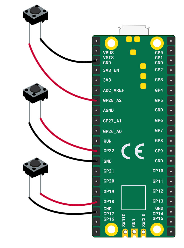


Comments