


Hardware components | ||||||
| × | 1 | ||||
Software apps and online services | ||||||
 |
| |||||
| ||||||
Hand tools and fabrication machines | ||||||
| ||||||
So I consider myself to be an absolute rookie in terms of Electrical Engineering and IoT related topics. In fact, I only just created my first PCB a week ago (not used in this project I bought this one). I have been so fascinated by all these little WiFi chips coming out and what can be done with them. So after doing some research on some different circuits that could be used to control a garage door, and prototyping on the breadboard, and even going into Eagle to design a PCB; I stumbled into a website called ControlEverything.
These folks are simply brilliant! They offer pretty much everything that I needed in the vary PCB I was designing only with quite a bit extra. After even more digging I found Hackster! Wouldn't you know they had a project using the PCB I planned to purchase from ControlEverything! To make the deal sweater is they have videos and an existing code library to use.
Their project had been setup using an Android based phone and I'm on iOS (not that is super relevant). This was all fine and dandy but I wanted to go a little bit further with this build. I needed to know whether my garage door is closed or open without being there.
Open or Closed? How do we find that out?Most garage door openers have some sort of system in place to detect the open or closed door status already in place. But we need a way to make this known to the Particle device. With the ControlEverything board this was easy.
So I went out to the garage and looked on the rail/door opener guide to see if the was any sort of reed switch or those little lever switches at either end and there was none. So I took the motor housing apart (unplug the opener first!!!) and found this little doo-dad. So I went on Google and found this part on several garage door repair parts sites. Basically this switch talks to the garage door opener logic board and tells when to stop opening or closing. So I plugged the opener back in and watched it work. Pretty clever!
The next logical step was to measure a voltage signal (not really smart if you don't have your multimeter set right) to see what each contact point would read when open/closed. I have one those low priced meters bought from Lowes that automatically reads AC or DC which sort of bothers me a little. At this risk of hurting my meter I tested anyway in the name of science!!! Okay that was lame...
Turn out that when for example the door is closed, the open contacts would read a range of 1.8mV to 100mV and the closed contacts would read a steady 5.05V. Well that to me seemed like a pretty reasonable way to say the CE board could treat these reading as either a 1 or a 0 (HIGH or LOW) logic.
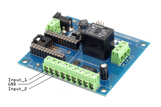
Well time to hook it up!So essentially what I did was splice into the Yellow, Brown, and Grey wire (pictured on the open/closed switch above) and hooked them up to the inputs 1, GND, and 2. Using the Particle Build IDE I located the library provided by CE and flashed it to the device and then went to IFTTT and setup a couple recipes tell me via SMS (or iOS notification) when inputs 1 or 2 went to the "ON" status. From this point I formatted the recipes to tell me "Garage door is opened" or "Garage door is closed" via SMS. Taking it a step further I used an iOS GPS recipe in IFTTT to say that when I got within a certain distance from my house to toggle the relay and open the door so I can pull right in. Speaking in terms of security this may not be best but I had to see if it worked plus I have someone there to monitor my house at all hours of the day. Like I said, IN THE NAME OF SCIENCE!!!
So in the near future I am going to keep testing and finding ways to improve on this. For example, I plan to setup some Particle Variables to make the OPEN/CLOSED status of my door something I can easily get by pulling a UI so I can check on it whenever I want. I also plan to 3D print a nice little enclosure module that the CE board can be in with an antenna and attached it the opener housing and make it cleaner in terms of install appearance.
I would suggest to CE to make the screen on the PCB easier to read as the green terminal block virtually covers them up thus making it hard to tell which GPIO is which. But hey, they give you a free Photon and a super nice and long USB cable with your purchase of their sweet PCB!


Comments