

Hardware components | ||||||
| × | 1 | ||||
| × | 1 | ||||
| × | 1 | ||||
| × | 1 | ||||
| × | 1 | ||||
| × | 1 | ||||
| × | 1 | ||||
| × | 1 | ||||
| × | 1 | ||||
| × | 1 | ||||
| × | 1 | ||||
Hand tools and fabrication machines | ||||||
 |
| |||||
 |
| |||||
Hi all, this is my first Hackster.io project, well probably my first anywhere actually. Not exactly sure where to begin, a real short story is I had a Cheap Yellow Display (CYD) laying around, I had also previously built a Galagino arcade cabinet. The CYD is supported by Galagino but the CYD lacks GPIO for controls, however it does have i2c, the official support for CYD in Galagino is to use a Wii remote, but that doesnt work well in an arcade cabinet.
For those that dont know a CYD is essentially a very well priced ESP32 board that includes a 2.8" touchscreen, SD card slot, sound output (although not that great) as well as some other IO. We dont actually use much of it in this project, really just the screen, sound & obviously the ESP32. The actual name is the "ESP32-2432S028R" but that isnt as catchy as CYD. Theres a lot of information here: https://github.com/witnessmenow/ESP32-Cheap-Yellow-Display
So I did a little bit of Googling to see if there were any i2c GPIO expanders or even such a thing, I came across a MCP23017, which were also fairly inexpensive and easy to get on Aliexpress. I created a breadboard setup and basically asked AI to help (i.e. do) with the code to convert the existing Wii remote i2c code to allow the MCP23017 to control it. After some trial and error, it worked.
I have also recently got into PCB design and this felt like a good project so designed a control panel PCB, where you attach the MCP23017, some buttons and a joystick. Initially I had grand plans of soldering a MCP23017 chip directly to the PCB but the actual chips are not as cheap as the breakout boards and are roughly the same size as the control panel anyway. Its a lot easier to solder the breakout board than desolder the chip and resolder to the PCB!
Next part was designing a case, the previous Galagino cabinet I built was based on a laser cut ply cabinet converted to 3D printing, it went together in the end but it was extremely tight, required lots of sanding/filing and probably wont ever come apart again so wanted to design something new, which screwed together for easy access if needed. It was a bigger pain that I initially realised, turns out designing something with multiple parts isnt easy! who knew! I wanted it so you could print all parts face down so you could use textured build plates to make it a little less 3D printed looking. It probably would had been a lot easier if I designed most of the case in one print but then you would see every layer line and that wasnt the original idea.
I would start off by flashing the CYD first, it's not super easy to compile as you need to supply the required rom files to be compiled. I would recommend taking a read through the software section of the official Github: https://github.com/harbaum/galagino this covers the roms needed and how to convert them to the required format. This is only needed to be done once, you dont need all the roms if theres certain ones you dont want. You will also need to install the Adafruit MCP23017 library, you can do this from library manager.
A few tips on compiling, use Arduino IDE however the latest ESP32 v3.x doesnt work properly, so downgrade this to v2.x, its recommended to use 2.0.9. You may also run into issues with space when compiling, if you do this, set the partition scheme to 'Huge APP. Once compiled and flashed via Arduino IDE and you can see the menu screen, it should be black, if its white there are options to invert this.
Obviously when you compile you will need to use my fork which has all changes to the i2c and also CYD options preset. https://github.com/DynaMight1124/galagino-MCP23017/tree/CYD-MCP23017
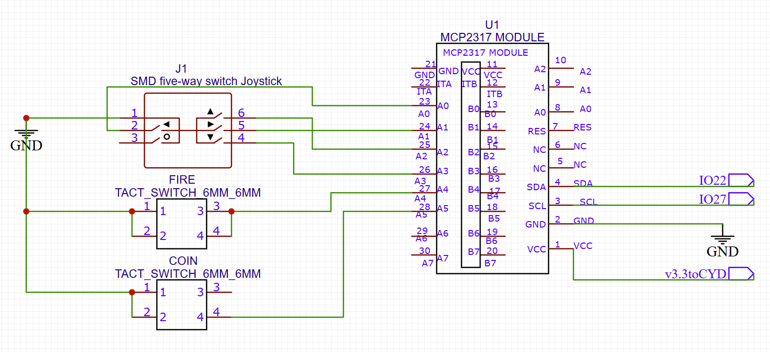
Control PanelNext up is building the control panel, make sure you have the required components:
I would recommend soldering the 'COIN' button first as you need to ensure the underside is as flush as you can get it since the MCP i2c board sits flush the otherside. I have been pushing the tach switch legs through the board, snipping flush, removing from the board then snipping back a little further, refitting then soldering.
To be honest, the MCP board doesnt actually need to be flush, you could solder this with the included pin headers as theres plenty of space in the cabinet but the included instructions are to solder flush :) after you've soldered the COIN button and its nice and flush, solder the fire and joysticks on the PCB, then its time to solder the MCP23017.
For this, theres a few methods, you could flood fill the points, which is perfectly fine as long as you've managed to get the board totally flat. Personally I've been using the pin headers that came with it but using the long end until its about half a mil through the PCB control panel then soldering one pin ensuring all the other pins are even then soldering each pin, after that snipping the other end flush and then soldering the other end, this keeps the soldering flush but has good connectivity through the two boards. You also dont need to solder every point, check the pictures of which I have soldered up, but no harm is soldering all of them.
The last part is the CN1 connector, when you got your CYD they include a JST cable with Dupont connectors, if you still have this then solder a 4x pin header to the underside so you can plug in the Dupont connectors, if you dont have the included JST cable then just solder the wires directly ensuring the wiring matches.
You may notice theres some pins for 'START' the original project has Fire, Start and Coin, usually Fire and Start are on the control panel with a Coin button at the front, where you'd put your coins in on a real arcade. However with the CYD the Coin button acts as start/coin and also reset if you hold it in so the additional start button wasnt needed and I never bothered looking to implement it but I've left it there incase its required in the future or whatever.
Theres also an optional marquee LED using 7 LEDs cut from a WS2812B IP30 144 LEDs per meter stripe. If you wish to use this, solder the JST connector as shown and plug into the connector at the top by the USB ports. Note that the wire colour doesnt match the usual combinations of ground/power/signal etc. Red = Power, Green = Ground & Black = TX/IO1 on the CYD. You can always repin the JST if that bugs you :)
I would recommend starting off by plugging in the connector from the control panel into CN1 on the CYD, I always forget this and its a little tight, which I obviously forgot to do in these pics too! then screw the CYD, front bezel and both sides together using 4x 10mm m3 bolts.
After that screw in the control panel 3D print & control panel PCB as shown below
Now I tend to just work around the cabinet to fit the remaining parts, just screw them in, ensuring they are lined up the best you can before screwing in fully as its fairly easy to screw into the plastic rather than hole.
If you choose the marquee LED it can be slotted between the gap
Onto the power side of things. It has a slot for the USB C connector, just push that in, then screw in the switch using the m2 screws. As for wiring, black goes to S1 on the CYD, red goes to the middle pole on the switch then another wire from the outside of the switch goes to S3 on the CYD
Now just plug it in, switch it on and everything should work!
So yeah, the sound... it isnt great. The CYD has known issues with sound due to poor design. It can be fixed if you replace a few components or half fixed by placing a 10k resistor across two legs of a chip, although this is still pretty terrible, just not as terrible as stock. The proper fix is here: https://github.com/hexeguitar/ESP32_TFT_PIO#audio-amp-gain-mod I've not personally tried it. I did the 10k resistor mod and this does help somewhat. I've tried to accommodate for the poor sound by using a small quieter speaker and removing any speaker holes from the case design as reduces the static noises, not an ideal solution but it is what it is! Theres also no volume control in the software. I will include a bottom STL with speaker holes if you need it but be warned, if you use a good size speaker with an unmodded CYD, it will not sound great.
Internal Battery? Portable?Yes this is possible and not too expensive, its not fully covered in this project but I have another similar project and I have got over 2.5hrs from a 500mAh lipo. A simple TP4056 lipo charger will handle charging the lipo and also powering the CYD etc. Link for the charger: https://www.aliexpress.com/item/1005005676862745.html
Battery wise theres loads of empty space, so you dont need to limit yourself to small batteries either. As for wiring, you can still use the projects USB port and switch.
The basics are: The projects USB C connector to +/- In on TP4056 (by the USB port), B+/- goes to the battery, OUT- goes to S1 on the CYD & OUT+ goes to the switch with the existing connection between the switch and S3 on the CYD.


Comments