

Hardware components | ||||||
 |
| × | 1 | |||
 |
| × | 1 | |||
 |
| × | 1 | |||
Looking for a smart way to charge your 12V battery without overcharging? This project shows you how to build a DIY 12V trickle charger with an auto cut-off feature using the widely available NE555 timer IC and a few basic components.
Perfect for lead-acid batteries, this circuit will automatically stop charging when the battery reaches full voltage, extending battery life and reducing energy waste.
🔧 Components List (Line by Line)NE555 Timer IC – 1 pc
- NE555 Timer IC – 1 pc
1N507 Diode – 1 pc
- 1N507 Diode – 1 pc
1NB62 Zener Diode (6.2V) – 1 pc
- 1NB62 Zener Diode (6.2V) – 1 pc
D36 Diode – 1 pc
- D36 Diode – 1 pc
- 10µF Electrolytic Capacitor – 1 pc
- Resistor 1kΩ – 1 pc
- Resistor 62Ω – 1 pc
- Resistor 4.7kΩ – 1 pc
- Resistor 10kΩ – 1 pc
- Resistor 12kΩ – 1 pc
- BC547 NPN Transistor – 1 pc
- 12V SPDT Relay (e.g., 650-1) – 1 pc
- Dual Color LED Indicator – 1 pc
- Freewheeling Diode – 1 pc
- 15V DC Adapter or Solar Panel – 1 pc
- Optional: Terminal blocks, enclosure
Discover Easy, Affordable, and Reliable PCB manufacturing with JLCPCB!Register to get $70 New customer coupons:https://jlcpcb.com/?from=EST
Special Deal: Get a $30 coupon for JLCPCB premium 6-layer PCBs: https://jlcpcb.com/6-layer-pcb?from=getcoupon
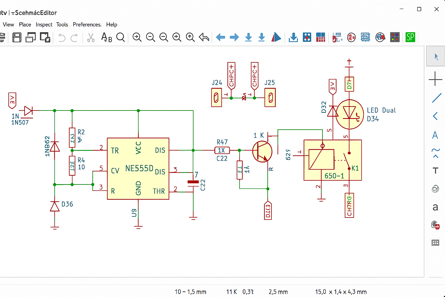
This project uses the NE555 IC as a voltage-level detector. When the battery voltage is below a set threshold, the output from the NE555 is high, which activates a transistor-driven relay to start charging the battery.
Once the battery is fully charged (typically around 13.7V to 14.2V), the NE555 detects the voltage via a resistor divider, switches the output low, and disconnects the charger via the relay, cutting off power to the battery.
⚙️ How It Works🔌 Power Input & Regulation- The 15V DC input is passed through protection diodes and a Zener to stabilize the voltage.
- This prevents reverse polarity and voltage spikes.
- Configured in comparator mode, the NE555 reads the divided battery voltage.
- If the voltage is below the threshold, the output goes HIGH, turning ON a transistor.
- The transistor switches the relay, which connects the charging source to the battery.
- A flyback diode is used to protect the transistor from voltage spikes.
- Once the battery voltage exceeds the set point, the NE555 output goes LOW.
- The transistor switches OFF, the relay disengages, and charging stops.
Here’s a schematic showing the complete layout:
Discover Easy, Affordable, and Reliable PCB manufacturing with JLCPCB!Register to get $70 New customer coupons:https://jlcpcb.com/?from=EST
Special Deal: Get a $30 coupon for JLCPCB premium 6-layer PCBs: https://jlcpcb.com/6-layer-pcb?from=getcoupon
🧪 Testing- Connect your 12V lead-acid battery to the output terminal.
- Power the circuit with a 15V adapter or solar panel.
- Observe the LED: ON = Charging, OFF = Full.
- Once charged, the relay will cut the power automatically.
- ✔️ Protects battery from overcharging
- ✔️ Fully automatic – no manual switching
- ✔️ Works with solar or adapter input
- ✔️ Simple, modular, and upgradable
- ✔️ Ideal for UPS, inverters, and emergency battery banks
This NE555-based trickle charger is a powerful little automation project for anyone managing lead-acid batteries. Whether you're running a solar setup or a DIY UPS, this build is cheap, effective, and simple to replicate.


Comments