

Hardware components | ||||||
 |
| × | 1 | |||
 |
| × | 1 | |||
 |
| × | 1 | |||
 |
| × | 1 | |||
 |
| × | 1 | |||
Component Quantity
- LM317 Voltage Regulator
- 1N5399 Diodes
- SRD-05VDC-SL-C Relay
- 4700µF Capacitor
- 47pF Capacitor
- 1kΩ Resistors
- 338Ω Variable Resistor (RP1)
- LED Indicators (5mm)
- Battery Connector
- Load Connector
- DC Barrel Jack
✅ Automatic load ON/OFF based on battery voltage
- ✅ Automatic load ON/OFF based on battery voltage
✅ Adjustable output voltage via LM317
- ✅ Adjustable output voltage via LM317
✅ Charge a12V lead-acid battery safely
- ✅ Charge a12V lead-acid battery safely
✅ LED indicators for charging and load status
- ✅ LED indicators for charging and load status
✅ Compact, single-layer PCB design
- ✅ Compact, single-layer PCB design
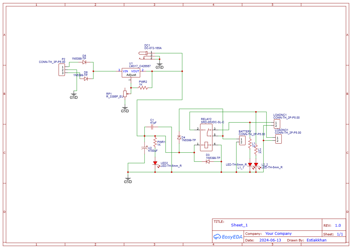
This schematic shows how the LM317 regulates voltage and controls a relay to automatically switch the connected load based on battery level.
Discover Easy, Affordable, and Reliable PCB manufacturing with JLCPCB!Register to get $70 New customer coupons:https://jlcpcb.com/?from=EST Special Deal: Get a $30 coupon for JLCPCB premium 6-layer PCBs: https://jlcpcb.com/6-layer-pcb?from=getcoupon
📦 PCB FilesDownload the Gerber File:
👉 Click to Download Gerber ZIP
🧾 PCB DesignTo ensure reliability and compactness, a single-layer PCB was designed for this project using EasyEDA. The layout accommodates all components neatly and includes:
Wide tracks for power lines
- Wide tracks for power lines
Proper diode orientation for protection
- Proper diode orientation for protection
Clear labeling for connectors (Battery, Load, DC Input)
- Clear labeling for connectors (Battery, Load, DC Input)
Heat sink space for LM317 if needed
- Heat sink space for LM317 if needed
You can use this file with PCB manufacturers like JLCPCB, PCBWay, or EasyEDA to fabricate your board.
⚙️ How It Works1. Charging ModeThe DC power input feeds the LM317 regulator.
- The DC power input feeds the LM317 regulator.
Voltage is adjusted via RP1 to safely charge a 12V lead-acid battery (typically 13.6V to 13.8V).
- Voltage is adjusted via RP1 to safely charge a 12V lead-acid battery (typically 13.6V to 13.8V).
LED1 lights up when charging is active.
- LED1 lights up when charging is active.
When the battery voltage is healthy, the relay activates and powers the load.
- When the battery voltage is healthy, the relay activates and powers the load.
If voltage drops below the set threshold, the relay disconnects the load to protect the battery.
- If voltage drops below the set threshold, the relay disconnects the load to protect the battery.
LED2 shows load status.
- LED2 shows load status.
Diodes D5, D6, and D3 protect against reverse polarity and relay back-EMF.
- Diodes D5, D6, and D3 protect against reverse polarity and relay back-EMF.
Emergency 12V Lighting
- Emergency 12V Lighting
DIY Mini UPS
- DIY Mini UPS
Battery Maintenance Station
- Battery Maintenance Station
Solar Power Backup System
- Solar Power Backup System
Use a heatsink on LM317 if drawing more than 1A.
- Use a heatsink on LM317 if drawing more than 1A.
Test voltage levels before connecting a battery.
- Test voltage levels before connecting a battery.
Enclose the PCB in a plastic casing for safety.
- Enclose the PCB in a plastic casing for safety.
If you're looking for a step-by-step build video, subscribe to our YouTube channel for Bangla DIY electronics tutorials!
Discover Easy, Affordable, and Reliable PCB manufacturing with JLCPCB!Register to get $70 New customer coupons:https://jlcpcb.com/?from=EST Special Deal: Get a $30 coupon for JLCPCB premium 6-layer PCBs: https://jlcpcb.com/6-layer-pcb?from=getcoupon
📌 ConclusionWith this simple yet effective DIY Mini IPS system, you can build your own automatic 12V load switch and charger. It's a great beginner project to learn about power electronics, voltage regulation, and PCB design.
Let me know if you make one yourself — I’d love to see it!


Comments