

Frequent load shedding or power cuts can disrupt your internet, small DC appliances, or even essential mini inverter setups. Manually switching to battery power is inconvenient and can damage sensitive electronics due to sudden loss of power.
With this simple and effective Auto Changeover Circuit, your system will automatically switch from the main DC adapter to a battery when the electricity goes out — and switch back again when the power returns.
This project is ideal for:
12V WiFi routers
- 12V WiFi routers
220W mini inverters
- 220W mini inverters
DC LED lights
- DC LED lights
IoT devices
- IoT devices
Microcontroller boards (e.g., Arduino, ESP8266)
- Microcontroller boards (e.g., Arduino, ESP8266)
Let’s explore how this works and how to build it yourself!
🧰 Components List (Serial-Wise)Relay – SRD-05VDC-SL-C (5V SPDT Relay)
- Relay – SRD-05VDC-SL-C (5V SPDT Relay)
Diode D1 – 1N4007 (Relay coil protection – flyback diode)
- Diode D1 – 1N4007 (Relay coil protection – flyback diode)
Diode D2 – 6A10 (High current diode to prevent reverse current)
- Diode D2 – 6A10 (High current diode to prevent reverse current)
Resistor R1 – 1kΩ (for LED2 – Power Indicator)
- Resistor R1 – 1kΩ (for LED2 – Power Indicator)
Resistor R2 – 1kΩ (for LED1 – Battery Indicator)
- Resistor R2 – 1kΩ (for LED1 – Battery Indicator)
Resistor R3 – 1kΩ (for LED3 – NO Mode Indicator)
- Resistor R3 – 1kΩ (for LED3 – NO Mode Indicator)
LED1 – Red 5mm LED (Battery mode indication – NC)
- LED1 – Red 5mm LED (Battery mode indication – NC)
LED2 – Red 5mm LED (Indicates adapter ON)
- LED2 – Red 5mm LED (Indicates adapter ON)
LED3 – Red 5mm LED (Indicates NO load active)
- LED3 – Red 5mm LED (Indicates NO load active)
DC Power Socket – 5.5mm barrel jack (12V input from adapter)
- DC Power Socket – 5.5mm barrel jack (12V input from adapter)
Battery Connector – 2-pin terminal block (connect to 12V battery)
- Battery Connector – 2-pin terminal block (connect to 12V battery)
NC Output Terminal – 2-pin block (for battery mode load)
- NC Output Terminal – 2-pin block (for battery mode load)
NO Output Terminal – 2-pin block (for adapter mode load)
- NO Output Terminal – 2-pin block (for adapter mode load)
PCB or Breadboard – For assembly
- PCB or Breadboard – For assembly
Jumper Wires – To complete all the connections
- Jumper Wires – To complete all the connections
Discover Easy, Affordable, and Reliable PCB manufacturing with JLCPCB!Register to get $70 New customer coupons:https://jlcpcb.com/?from=EST Special Deal: Get a $30 coupon for JLCPCB premium 6-layer PCBs: https://jlcpcb.com/6-layer-pcb?from=getcoupon
This circuit smartly uses a Single Pole Double Throw (SPDT) relay to toggle between two 12V power sources:
A DC adapter (main supply)
- A DC adapter (main supply)
A 12V battery (backup)
- A 12V battery (backup)
When the adapter is ON, it powers the relay coil. This switches the internal contact from NC (Normally Closed) to NO (Normally Open), allowing the load (like a router or inverter) to run on adapter power.
When the adapter is OFF (power cut):
The relay coil turns off
- The relay coil turns off
Internal switch flips back to NC
- Internal switch flips back to NC
Load automatically shifts to draw power from the battery
- Load automatically shifts to draw power from the battery
There’s no switch delay, no power flicker, and no manual effort. The transition is seamless and silent.
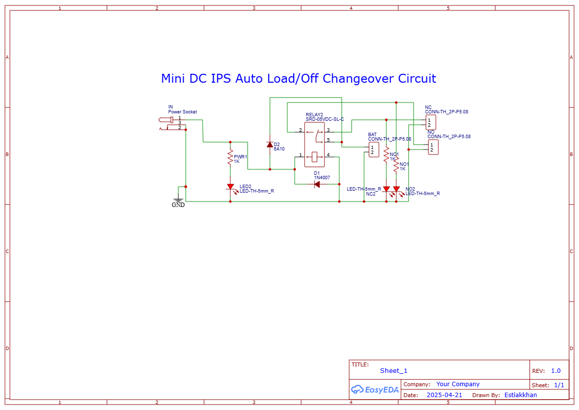
🔄 Detailed Circuit Diagram Explanation
At the center of this system is the SRD-05VDC-SL-C relay, which acts as an automatic switch. The adapter’s 12V output energizes the relay coil via pins 2 and 5, causing the relay to connect its common terminal (pin 3) to the Normally Open (NO) terminal (pin 1). This allows the load to operate from the adapter power during normal electricity.
When the adapter power fails:
The relay coil loses power
- The relay coil loses power
The internal switch flips back to the Normally Closed (NC) terminal (pin 4)
- The internal switch flips back to the Normally Closed (NC) terminal (pin 4)
The load now draws power directly from the 12V battery connected to the NC pin
- The load now draws power directly from the 12V battery connected to the NC pin
A 1N4007 diode (D1) is placed across the coil terminals to absorb reverse EMF spikes generated when the coil de-energizes. Without this diode, the relay could fail prematurely.
A 6A10 diode (D2) is placed in series with the adapter line to prevent current from flowing backward into the adapter when the battery is active.
To indicate system status:
LED2 turns on when the adapter is present
- LED2 turns on when the adapter is present
LED3 turns on when the relay is energized (NO mode active)
- LED3 turns on when the relay is energized (NO mode active)
LED1 lights up when battery backup is running (NC mode)
- LED1 lights up when battery backup is running (NC mode)
Each LED is current-limited by a 1kΩ resistor.
💡 Use CasesThis auto changeover system can be used for:
WiFi Routers – ensure uninterrupted internet
- WiFi Routers – ensure uninterrupted internet
LED Lighting – automatic light switching in homes or stores
- LED Lighting – automatic light switching in homes or stores
Mini IPS Systems – smooth 220W inverter backup
- Mini IPS Systems – smooth 220W inverter backup
Smart Devices – continuous power for microcontroller/IoT setups
- Smart Devices – continuous power for microcontroller/IoT setups
You can use a relay module or build on a breadboard/PCB
- You can use a relay module or build on a breadboard/PCB
Solder all joints cleanly and isolate the adapter and battery grounds if needed
- Solder all joints cleanly and isolate the adapter and battery grounds if needed
Use thick gauge wire for inverter or high-current outputs
- Use thick gauge wire for inverter or high-current outputs
Make sure the battery and adapter are both regulated to 12V
- Make sure the battery and adapter are both regulated to 12V
Protect the battery with a fuse (recommended)
- Protect the battery with a fuse (recommended)
Do not exceed the relay’s current limit (~10A max)
- Do not exceed the relay’s current limit (~10A max)
Always double-check the diode orientation
- Always double-check the diode orientation
Use proper heat dissipation if load >150W
- Use proper heat dissipation if load >150W
Add a fuse or polyfuse to the battery line to avoid short circuits
- Add a fuse or polyfuse to the battery line to avoid short circuits
For outdoor or permanent use, place the circuit inside a plastic enclosure
- For outdoor or permanent use, place the circuit inside a plastic enclosure
Discover Easy, Affordable, and Reliable PCB manufacturing with JLCPCB!Register to get $70 New customer coupons:https://jlcpcb.com/?from=EST Special Deal: Get a $30 coupon for JLCPCB premium 6-layer PCBs: https://jlcpcb.com/6-layer-pcb?from=getcoupon
🔋 Build Your Own Auto Load Changeover Circuit for Inverters & Routers!✅ Live Load Test with 220W Inverter✅ LED Indicator Working✅ Perfect for Bangladesh Load Shedding📺 Subscribe for More: EST Experiments YouTube Channel
🔋 Build Your Own Auto Load Changeover Circuit for Inverters & Routers!✅ Live Load Test with 220W Inverter✅ LED Indicator Working✅ Perfect for Bangladesh Load Shedding📺 Subscribe for More: EST Experiments YouTube Channel📝 Final Words
This project is simple but extremely useful — especially in regions like Bangladesh where load shedding is common. With this relay-based auto switch, you no longer need to worry about manually flipping switches or losing your router connection.
Just plug, connect, and let it work automatically — saving time and protecting your devices.
Need a CapCut video template, YouTube thumbnail, or Bangla eBook of this project? Let us know. We’re happy to help!


Comments