


Hardware components | ||||||
 |
| × | 1 | |||
 |
| × | 3 | |||
|
| × | 4 | |||
 |
| × | 1 | |||
 |
| × | 1 | |||
 |
| × | 1 | |||
Software apps and online services | ||||||
 |
| |||||
Hand tools and fabrication machines | ||||||
 |
| |||||
The idea behind this Smart Candy dispenser (or Gumball Machine) was to create a Halloween project that was playful for the kids and I didn't need to be there for kids to have candy !
The concept is simple: speak a cookie-related phrase, and if it's good enough, you get a treat!
The following are the steps needed to build this.
All the files are available at the Github project page. There you'll also find more instructions on how to build and run this.
To get all the files, clone the repository.
Hardware UsedClient- Seeed Studio Xiao ESP32S3 Sense
- Seeed Studio Round Display for Xiao
- DC N20 Geared Motor 6v
- MX1508 motor driver
- 4x M2x7mm screws (4x 4.5mm wide x 3mm length threaded insert)
- 3x M3x12mm screws (3x 3.5mm wide x 2mm length threaded insert)
- 3D Printer
- Seeed Studio reComputer j4012
- Python
- Docker (and docker compose)
For the server, any machine will do, but if it has a GPU with CUDA, the better. If you don't have a GPU Cuda capable, the CPU can also be used - but it will be considerable slower.
Software- Arduino IDE
- LVGL
- TFT_eSPI (configured for Xiao Round display)
- ArduinoJSON
- PNGdec
- Wire
- CHS6X_Touch (custom library - Xiao Round Display Touch Screen)
- cookie.h (custom library - cookie image)
- no_cookies.h (custom library - no cookie image)
1. - The user touches the Xiao Round Screen
2. - It then records a 5s phrase - this is when you speak the cookie based phrase, like - "I love cookies", or, " To much cookies give me a sugar rush".
3. - The recording is sent to the server
3.1. - It's automatically transcribed using Whisper (language is configurable)
3.2. - Classifies the phrase as positive or negative about chocolates or candy
4. - If the phrase is positive, a candy is dispensed
5. - Otherwise, please try again.
When you connect the Candy dispenser, it starts with the standby animation
When you touch the display, it starts recording your phrase
After recording your phrase, it sends the data to the server and waits for a response.
If the response is positive, a candy is dispensed, and we see cookies in the display.
If the response is negative, no cookie is given.
To make things easier, the deployment is done with docker compose (You can create a virtual environment with Python and use uvicorn and systemd to start at boot, if docker is not your thing).
Deployment with docker composeFor GPU use:
- NVIDIA drivers installed
- nvidia-container-toolkit: official guide
Use your distro package management to install the nvidia-container-toolkit.
Example using Ubuntu:
sudo apt-get install -y nvidia-container-toolkit
sudo systemctl restart docker
To build the image, I've prepared two files to use:
- docker-compose.gpu.yml (to use with GPU)
- docker-compose.cpu.yml (to use with CPU)
The following steps are the same, for GPU or CPU. Change only the compose filename.
docker compose -f docker-compose.gpu.yml up --buildThis will build the image and run it. It will take some time to build the image.
After the image is up and running, ctrl + c will stop it.
To run it again, just run
docker compose -f docker-compose.gpu.yml upWhen this is done, it will listen on 0.0.0.0, port 8000.
Autostart
For the docker image to start at boot, we need to create a Systemd file. Let's create the file
sudo vi /etc/systemd/system/candy-machine.serviceInside, place the following lines. Here I'm using the docker compose GPU file.
Don't forget to replace the location for your working directory, where the docker compose files are located.
[Unit]
Description=Candy Machine API (Docker Compose)
Requires=docker.service
After=docker.service

[Service]
Type=oneshot
RemainAfterExit=yes
WorkingDirectory=/path/for/the/project
ExecStart=/usr/bin/docker compose -f docker-compose.cpu.yml up -d
ExecStop=/usr/bin/docker compose -f docker-compose.cpu.yml down
TimeoutStartSec=0

[Install]
WantedBy=multi-user.target
Reload Systemd and enable the new service.
sudo systemctl daemon-reexec
sudo systemctl daemon-reload
sudo systemctl enable candy-machine.service
Start it manually the first time.
sudo systemctl start candy-machine.serviceNow, the Candy Machine will start automatically when the system starts.
ClientFor the client, I went with the Xiao ESP32S3 Sense.
Despite its tiny form factor, the XIAO ESP32S3 Sense handles everything — from Wi-Fi and I2S audio capture to real-time sprite rendering on the Round display for Xiao — all thanks to FreeRTOS.
It had to be the Sense version because of it's characteristics:
- Microphone
- Flash size
- PSRAM
I had to make use of the PSRAM for the recording - it records the 5s phrase in memory and then it sends it to the server for further processing.
Because of all the animations and images, without the PSRAM, I had no memory left.
When the Arduino IDE gave an error because there was no memory available, that was a problem that I thought I couldn't solve.
Until, a certain LLM gave me the idea of PSRAM. How could I didn't thought of that ?
Arduino IDEWe need to configure the Arduino IDE and some options for the ESP32S3 Sense and to make use of the previous features.
Under tools, set the following options:
- PSRAM
- Flash Size
You can't change much regarding the Xiao Pins.
Some are used by the Sense, others by the Round Display, I2C, etc.
There aren't many available.
You can read more about it on Seeed Studio Wiki:
https://wiki.seeedstudio.com/xiao_esp32s3_pin_multiplexing/
https://wiki.seeedstudio.com/xiao_esp32s3_getting_started/
BuildingThis project needs a 3D printer for the parts - all Candy dispenser parts are 3D printed. In the 3D folder, in the Github project, you'll find all the files needed.
You'll need:
- the base
- the electronics cover
- the rotating cylinder
- the DC motor support
- the candy jar
- the candy jar lid
For the assembly, we need all the things listed in the things tab.
PowerThis candy machine is to be powered by 5v. There's a wiring passage from the bottom, where the power jack will be, to the front of the base, to the electronics components.
First, let's pass 2 wires through. You can insert the wires from the bottom or from the front of the base. There's no right order.
Now, let's wire the female DC power jack. Using a soldering iron, solder the positive wire to the middle connector and the ground to the connector on the side. At least this is the way this jack is wired internally. Check yours.
You may need a bit of strength to securely place the power jack. It's a tight fit.
Use a right angle DC male power jack connector. Insert the wire in the guide.
Next version will feature a USB-C connector instead of a 3.5 power jack.
InsertsFor the screws we're going to use, it's better to use threaded inserts. You need 7 of those.
- 3x 3.5mm x 2mm ( 2mm x 7mm screws)
- 4x 4, 5mm x 3mm ( 3mm x 12mm screws)
The smaller inserts (3x) are put into the electronics support, to attach the DC motor support. Use your soldering iron to press the inserts into the 3D print.
The 4x inserts are used in the base, where the electronics will be attached.
Now, let's insert the F625z flange into the base for the cylinder rotation. It will help it rotate smoothly.
Press it into the hole. The wider side is facing the hole for the cylinder.
Later, we will glue it to the motor shaft.
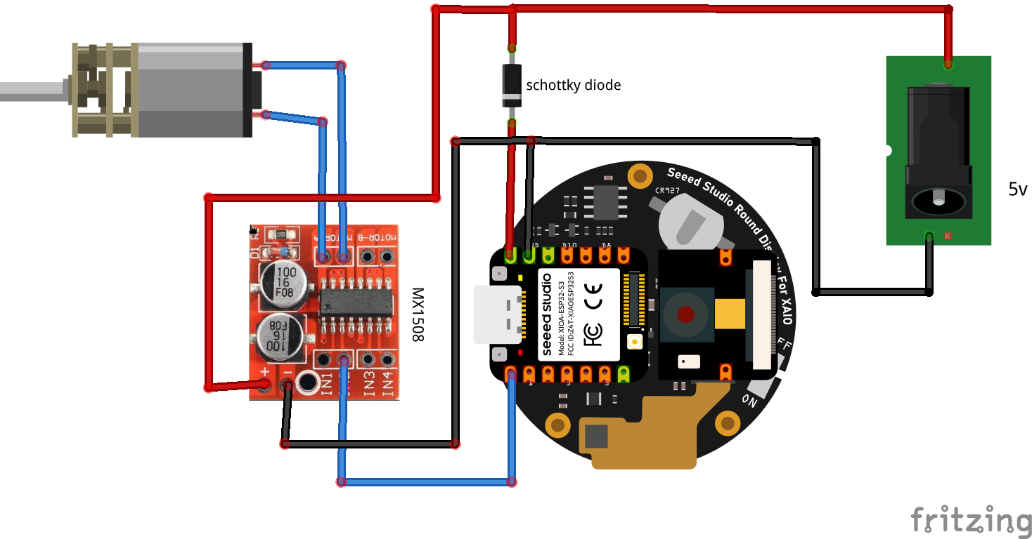
The ElectronicsThis is the brains of it all.
You will need:
- DC motor 6v, low RPM
- MX1508 motor driver
- 1x Schotty diode
- Xiao ESP32S3 Sense
- Round display for Xiao
At this point, you should already had the red/black wires through the hole from the bottom of the base to the front, where the electronics will go.
Here's how to install everything correctly.
The round display for Xiao is inserted from the front and use screws to secure it. There's only one way to secure it. This way, we guarantee that it stays upright.
Next, from the back, after you wire everything (below are the instructions), you can secure the motor using the motor support. The Xiao ESP32S3 Sense (you need one with headers) will be secured to the round display for Xiao.
Wire the motor to the motor driver. You can now place the motor in the electronics base and screw the motor holder lid.
Following the schematics, wire it all.
Regarding the PIN usage, we pretty much just use the one Pin - D0, that's going to connect to IN2 to the MX1508.
To place everything in, just insert the cylinder in the motor shaft (you can put a dab of glue now), tuck the wires better and secure the electronics cover.
Motor timingNow that everything is assembled, let's run a test program so you can time exactly how long the motor must run for a full cylinder rotation.
This way, we don't need the cylinder hole to align with the candy exit from the recipient. With a full rotation, we guarantee that a candy always exits (at least in theory :).
NOTE: Except for the first time, we need to "play" twice. The first time there's no candy and we need a candy to enter the hole.
//PIN where the MX1508 IN2 is connected

#define IN2 D0
void setup() {
    pinMode(IN2, OUTPUT);
    digitalWrite(IN2, LOW);
    Serial.begin(115200);
    delay(1000);
    Serial.println("Motor rotation testing started!");
}
void loop() {
    // Starts rotating
    digitalWrite(IN2, HIGH);
    Serial.println("Motor started");
    delay(2000); // This is the timing to adjust

    // stop
    digitalWrite(IN2, LOW);
    Serial.println("Motor stopped");
    delay(1000);
}
Play with the timing so a full rotation is archived.
After that, change the timing in the arduino code and upload it to the Xiao.
Tuck the cables and close the electronics panel.
You're ready for it.
Here's a video with the Candy Dispenser working
TODO- Add a sensor to detect a candy has exited.
- Migrate the FastAPI server to work with a Raspbery PI AI Hat+ when, and if, it supports general LLMs.
- Check for no network directly on the Xiao


_3u05Tpwasz.png?auto=compress%2Cformat&w=40&h=40&fit=fillmax&bg=fff&dpr=2)


Comments