
Hardware components | ||||||
 |
| × | 1 | |||
 |
| × | 1 | |||
 |
| × | 1 | |||
| × | 5 | ||||
 |
| × | 1 | |||
Software apps and online services | ||||||
| ||||||
| ||||||
Hand tools and fabrication machines | ||||||
 |
| |||||
 |
| |||||
 |
| |||||
 |
| |||||
 |
| |||||
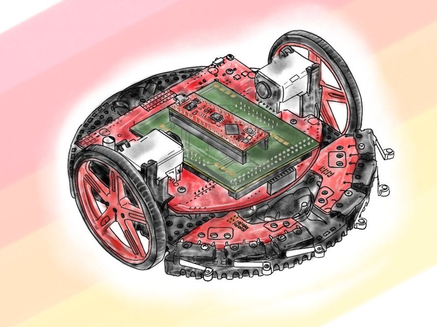
For our Senior Design class, we were assigned this project. Our sponsor, Texas Instruments, asked us to design and fabricate a PCB (printed circuit board) to interface the chassis board on the TI RSLK MAX with a low-costFPGA. This would expand the educational use case of this product to serve for digital logic design in addition to embedded systems.
As electrical and computer engineering students we saw this project to be very valuable. Our experience in digital logic design classes, had very few "hands on" experiences; we would usually have labs involving an FPGA flipping switches and turning on LEDs. Using the TI RSLK MAX chassis board serves as a motivational platform for students to learn more about FPGAs and logic circuits.
Main Product Requirements- Design and implement a PCB that can interface the TI-RSLK chassis board with a low-cost FPGA.
- Design and write six example programs that implement all subsystems.
- Write six labs intended to teach the user digital logic design with the TI-RSLK
Texas Instruments offers the TI RSLK MAX kit as an educational tool to teach students about robotics and embedded systems. On their website, they offer various modules that serve as educational tools to learn about every subsystem and how to use them. Our goal is to offer a similar experience for students with digital logic design. As previously stated, this kit serves as a good platform for FPGA education, the robot includes:
- 4 onboard LEDs
- 6 active-low bumper switches
- 8-channel infrared line sensor array
- Two DC brushed motors
- Encoder for each wheel
WebFPGA is a startup company that makes FPGA use easy and accessible to everyone, which goes along with what our goal is for this project. As per their Kickstarter page:
WebFPGA is a cloud-based development environment for FPGAs with compatible development boards. Our software toolchain uses a recent browser technology called WebUSB to program the FPGA, without any software required other than a modern web browser (Chrome/Opera/Edge75 supported for now). We also provide a browser-less, command-line solution.
Some of the features of this FPGA board
- 32 Input Output
- Neopixel RGB LED
- User switch
- Reset
- 5V and 3.3V output
- 16MHz clock
Along with their hardware, they offer a responsive support forum, online IDE, and documentation on their website. All these features make this FPGA board the perfect candidate for this project, and other future user projects.
System Design
This system design diagram illustrates the overall use of this project. In the diagram, we can start from the RSLK which has most of the sensors and actuators. The PCB adapter routes all IO supplies the WebFPGA with power. From there, the WebFPGA can be connected to a PC through the MicroUSB port where a student can synthesize and flash their Verilog programs using the CLI (Command Line Interface) with a local synthesis engine, or the online IDE which uses WebFPGA's cloud based synthesis engine.
HardwareAttached to this page is a document labeled PCB Datasheet. It demonstrates the connections between each pin of the WebFPGA and the corresponding connections with the TI RSLK. This reference can serve as a guide for understanding this project. The document contains screenshots taken from the CAD files and gives a short explanation of various functionalities. Overall, there are two 1x20 female headers, two 2x10 female headers, one 2x20 female header, 1 Schottky diode, and five 100kΩ resistors. The diode and resistors are surface mount components and may require a hot air gun or heated plate for soldering installation. More information on the components can also be found on the sheet.
As per one of the requirements, we designed a PCB that can easily interface between the RSLK and the WebFPGA. The design files for the PCB are attached to this page. These are EAGLE CAD files, and we recommend you open them using Eagle or Fusion 360, both of which can come with a free trial - or if you are a student a free version. On the schematic file, there are two sheets. The first sheet shows the connections made to the RSLK while the second sheet shows connections made to the WebFPGA. The PCB is powered by the RSLK and routes power from the RSLK to the WebFPGA. The diode on the PCB serves as a barrier from power from the WebFPGA's MicroUSB going back to the RSLK. If soldered correctly, the entirety of the PCB should be easily removed from the RSLK. There are also fourteen different test pads on the PCB. These test pads are there for your convenience. Using a simple voltmeter, you would be able to test whether everything is connected as it should be. For example, the QTR signals should read 2.5V if they are being used. Testing the power of the PCB or the WebFPGA should get a reading of 5V.
Note:Ensure when soldering your diode, you have the direction notch facing to the left side if looking at the PCB straight on.
SoftwareAs per one of the requirements we have provided six example programs attached below, each program shows the use of each individual subsystem on the RSLK. The folder contains a README file that contains information on how the directory is organized, how to understand it, and how to use it.
LabsBelow are links to each individual lab. It is important to note that to get the best learning experience, only use the code snippets given in the individual labs. The attached repository contains code examples which has the answers for some of the labs.
- Lab 1: Setup
- Lab 2: Intro to Verilog Programming
- Lab 3: Clocks and Timing
- Lab 4: Motors and Movement
- Lab 5: Encoders and Precision Movement
- Lab 6: IR Sensors and Line Following


Comments