


Hardware components | ||||||
 |
| × | 1 | |||
 |
| × | 2 | |||
 |
| × | 1 | |||
 |
| × | 1 | |||
 |
| × | 1 | |||
 |
| × | 1 | |||
 |
| × | 1 | |||
 |
| × | 1 | |||
 |
| × | 1 | |||
Software apps and online services | ||||||
| ||||||
 |
| |||||
Hand tools and fabrication machines | ||||||
 |
| |||||
This project simulates a basic smart home system using an ESP8266 that communicates via Wi-Fi with a mobile device through the SyncCanvas app. From the app, you can control:
- A basic LED (on/off)
- A dimmable LED (PWM)
- A buzzer as an alarm
- A DHT11 sensor for temperature and humidity
All communication is done over TCP, with no need for cloud services or complex configurations.
🔢Step-by-Step InstructionsStep 1: Understand the Components
- LED (on/off): Digital control
- LED PWM: Brightness via analog PWM signal
- Buzzer: Emits sound when activated
- DHT11: Sends temperature and humidity data
- ESP8266: Main controller and Wi-Fi client
- Sync Canvas: Mobile app to send commands and display data
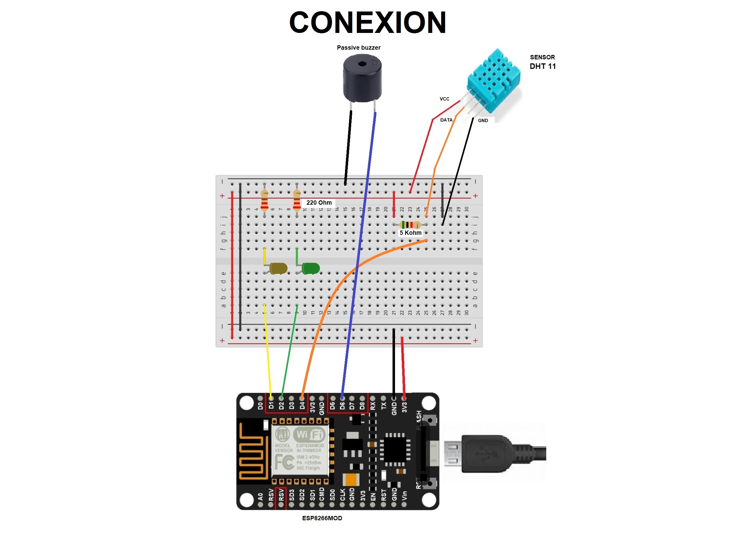
Step 2: Circuit Connections
ESP8266MOD Pinout:
- LED ON/OFF: GPIO5 (D1)
- LED PWM: GPIO4 (D2)
- Buzzer: GPIO12 (D6)
- DHT11 Sensor:
- VCC → 3.3V
- GND → GND
- Signal → GPIO2 (D4)
Step 3: Upload the Code
- Open Arduino IDE.
- Upload the provided code.
- Set your Wi-Fi network (SSID and password) and server IP/port as indicated in the app.
Step 4: Use the SyncCanvas App
Link App: https://play.google.com/store/apps/details?id=com.erko.synccanvas&pcampaignid=web_share
Open the app on your phone.
- Create a screen with buttons, a slider, a graph, and a text input.
- Set input/output parameters for each graphic element.
- Watch a reference video if needed.
Command Table for Communication:
Command Action
A Start DHT11 reading
B Stop DHT11 reading
C Turn ON LED (on/off)
D Turn OFF LED (on/off)
E Turn ON buzzer
F Turn OFF buzzer
LPxxx LED PWM brightness (0–255)
Step 5: Display Sensor Data
- When reading is active, the ESP8266 sends:
- Temperature:
TXX(XX = temperature from DHT11) - Humidity:
GTHXX(XX = humidity from DHT11) - These values can be shown inside the app.
Step 6: Experiment and Improve
- Change the DHT11 reading interval.
- Adjust maximum LED brightness.
- Modify buzzer tones.
- Add more elements in the app to expand your control panel.


Comments