


Do you need an isolated UART communication?Do you like to communicate wireless (BLE)?
After having former CYW20822P4TAI040 based version running I found some features needed for improvement, see here the differences between the previous and new version:
CYW20822P4TAI040 based:
- Voltage supply and IOs 3V3 only
- higher wireless distance
NEW:CYBLE-222014-01 / PSOC4BLE based:
- Voltage supply and IOs from 1.8V to 5.5V
- PCB (easier assembly)
- User configurable 4-pin interface
- shorter wireless distance
Both versions are based on Infineon's "AIROC™ EZ-Serial" platform, that enables an easy way to run serial communication via dedicated preconfigured Bluetooth® LE modules.
ElectronicsThe size of PSOC4 based BLE module CYBLE-222014-01 is only 10 x 10mm², and includes 256-KB flash memory, 32-KB SRAM memory, up to 16 GPIOs, one 12-bit/1-Msps SAR ADC, two SCBs (I2C, UART, SPI), four 16-bit timers (counter, PWM), I2S master, and Bluetooth 5.1 including an integrated on PCB antenna.
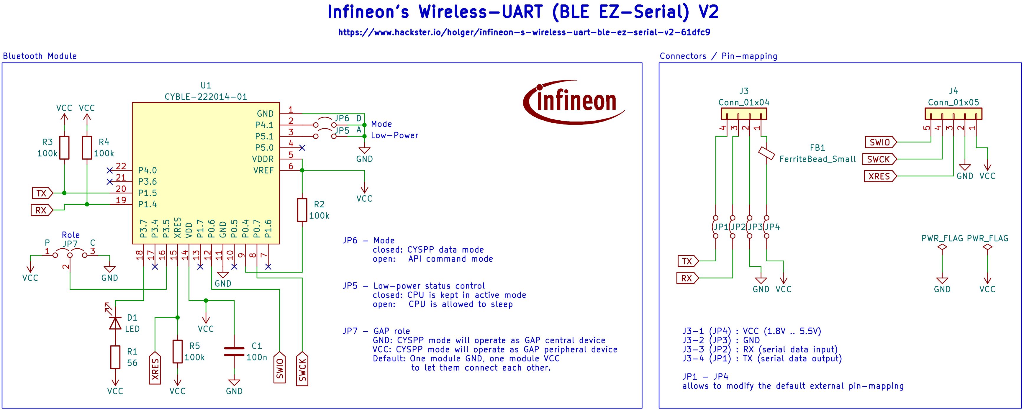
Infineon's "AIROC™ EZ-Serial" firmware requires a minimum external circuitry to get the module running in autonomous mode for serial bridging (JP6, CSYPP mode). A module pair need a GAP Peripheral and GAP Central, what will be user selected by JP7. Here the schematic, layout / PCB that has been developed:
The BOM is reduced to the following:
Infineon's CYBLE-222014-01 PSOC4 based BLE module
Würth Elektronik, WL-SMTW SMT TOP LED Waterclear ‘Blue’, 150141BS73100
Würth Elektronik, WR-PHD Angled 4-Pin THT Header 2.54 mm, 61300411021
Würth Elektronik, WCAP-CSGP Ceramic Capacitors, 100nF, 0603, 885012206020
Würth Elektronik, WRIS-RSKS Resistors, 56 Ohm, 0603, 560112116142
Würth Elektronik, WRIS-RSKS Resistors, 10k Ohm, 0603, 560112116005
Würth Elektronik, WRIS-RSKS Resistor, 100k Ohm, 0603, 560112116004, 4pcs
Würth Elektronik, WE-CBF SMT Ferrite Bead, 300 Ohm @100 Mhz, 74279264
The PCB can be ordered directly from the partner Aisler.net using this Link.
Note: Two assembled PCBs are needed, one configured as GAP Central (C: JP7:2-3, GND) and the other GAP Peripheral (P: JP7:1-2, VCC)
SoftwareAfter assembly, the PSOC4 module CYBLE-222014-01 needs to be programmed with the AIROC™ EZ-Serial firmware, actual version EZ-Serial_V1_1_1_CYBLE-222014-01.hex. This.hex file is the complete stack+app firmware image suitable for flashing via PSOC Programmer and the Serial Wire Debug (SWD) interface (P0.6, P0.7, XRES, VDDD, GND). For those who are not familiar with that, please refer to PSOC Creator IDE and its documentation or contact me.
User OperationAfter the firmware has flashed it runs out of the box by minimized user operation.
Note: Two assembled PCBs are needed:First, configured as GAP Central (C: JP7:2-3, GND)Second, configured as GAP Peripheral (P: JP7:1-2, VCC)
When powered up the blue LED shows the connection between both Modules.Note: When the power supply (specified 1.8V to 5.5V for the BLE module) becomes lower than the specified voltage of the LED, the communication will work, but no connection is shown visually by the LED. In this case, you can replace the blue LED by an LED for lower voltage operation.
When you connect two modules e.g. by using two USB-2-Serial converters to your PC than text messages can be written 'wireless'. Well, just a test scenario. In really you might equip your embedded system's UART with the BLE adapter and bridge to a PC or another embedded system's UART.
HousingAfter successful testing the modules can be encased.
Using FreeCAD several cases have been developed, and can be used depending on your 3D-printer.
If you have a multicolor printer then the pin description (TR-+) on the bottom case as well as the GAP function (P/C) on the top case can be colored. The (TR-+) on the top case's side is visible as relief.
Note: The given pin description is based on the original/default PCB, when the pin mapping is not changed by using the jumper JP1 - JP4.
Additionally, you can find a housing showing the Infineon Logo, so that you know which BLE device is inside.
SummaryOn the quick an existing serial (UART) communication can be replaced easily having the advantage of...
- wireless connection (e.g. less cables, through walls without a hole, etc.)
- galvanic isolation
The new version gives additional advantages...
- PSOC4 based version supports voltage range from 1.8V up to 5.5V what makes it more universal for many applications
- The new PCB enables easier assembly and more flexible 4-pin interface mapping by changing routing (VCC, GND, TX, RX).
Special thanks to Aisler for manufacturing the PCBs and to Würth Elektronik for providing the collateral parts.
Thanks to Valentyn for helping on this project.
Well - that's it!... for the moment. Stay tuned!
Regards, Holger


Comments