

Hardware components | ||||||
 |
| × | 1 | |||
 |
| × | 1 | |||
 |
| × | 1 | |||
 |
| × | 1 | |||
 |
| × | 1 | |||
 |
| × | 1 | |||
 |
| × | 1 | |||
 |
| × | 1 | |||
 |
| × | 1 | |||
Software apps and online services | ||||||
 |
| |||||
| ||||||
 |
| |||||
During pandemic situations it is appropriate to take general safety measures. When individuals surround and get in contact with many objects it may increase in spread of virus. So, I came with a idea of "A Smart Door Knocker" that alerts the person inside the house when someone approaches the house door. When an ousider approaches or emits a light source near the sensor then a buzzer beeps, light glows as indication and text message is sent to the owner.
Uses-
1. It is useful for individual security especially to girls when they are alone at home.
2.It is helpful to get inside the house without getting in contact with doorbell.
3.It helps to alert when someone approaches our house door.
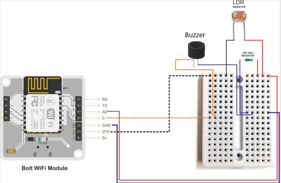
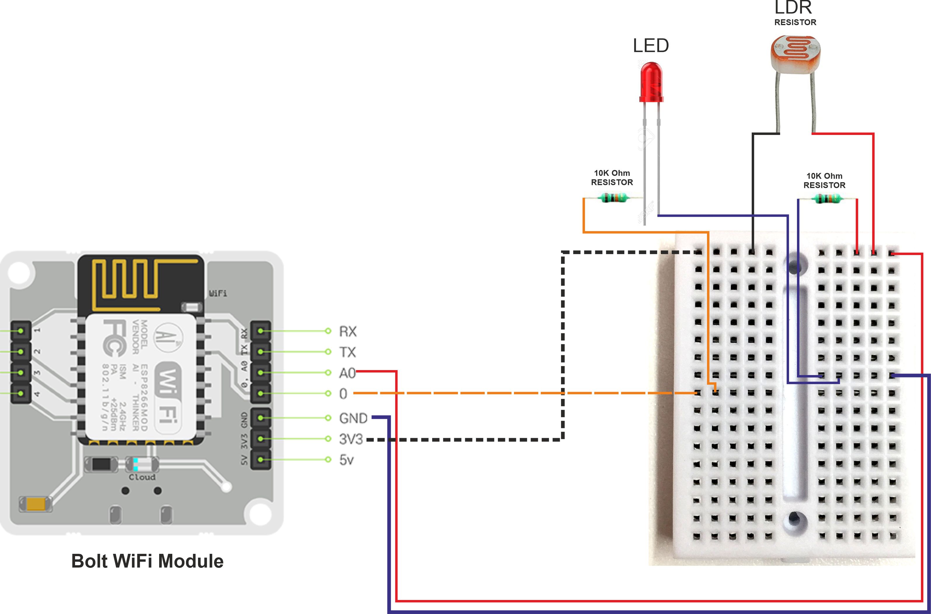
Hardware SetupRequirements-
Warning-Make sure the Bolt module is not powered on while making connections and Double-check all connections before turning it on.
Step 1 -Initially, connect breadboard with Bolt IoT WiFi Module pins with the help of Jumper Wires. Here we are going to use only four pins:
- 3v3 Pin
- A0 Pin
- GND Pin
- 0 Pin
Step 2-Insert one leg of the 10k Ohm resistor into the GND pin-connected row and another leg of the resistor into the A0 pin-connected row.
Step 3-Connect LDR resistor, as there is no positive or negative end for them. So we will Insert one leg of the LDR into the Bolt Module's 3v3 Pin-connected row of the breadboard and other into the A0 pin connected row.
Step 4- Connecting the LED to the Bolt.Take one leg of the resistor and wrap it around the longer leg of the LED i.e positive leg.Now, Insert the negative leg of the LED into the GND Pin-connected row of the breadboard. and Insert the other leg of the resistor in digital pin 0 connected row of the breadboard.
Step 5-Connecting the Buzzer with the help of male/female wire.Now, we will connect the negative leg of the buzzer (smaller leg) into the GND Pin-connected row of the breadboard. and connect the other leg of the buzzer (positive leg) in digital pin 0 connected row of the breadboard.
Step 6- Now we have all done with the connection, its time to safely power on the Bolt module.
Software Setup-
BOLT Setup
Go to cloud.boltiot.com and create a new product.
While creating the product, choose product type as Output Device and interface type as GPIO.
After creating the product, select the created product and then click on the configure icon.
select A0 in the hardware tab.
Now, Move to the code tab
and write the following code to control the LED and buzzer also.
<!DOCTYPE html>
<html>
<head>
<title>Bolt IoT Platform</title>
<script type="text/javascript" src="https://cloud.boltiot.com/static/js/boltCommands.js"></script>
<script>
setKey('{{ApiKey}}','{{Name}}');
</script>
</head>
<body>
<center>
<button onclick="digitalWrite(0, 'HIGH');">ON</button>
<button onclick="digitalWrite(0, 'LOW');">OFF</button>
</center>
</body>
</html>
Now save and exit the configuration and link this product with the Bolt Module.
and select the Device.
As we have created our LED product, configured it and linked it to our Bolt module, we will open Bolt mobile app and can see the below option by selecting our device.
where on click "ON" button, it will turn the LED on. Similarly, clicking on "OFF" button will turn LED off.
Note-It is same for buzzer and LED
2)Twilio Account Setup
Step 1-Open https://www.twilio.com/ In a browser.
Step 2: Click on Get a Free API Key button to sign up.
Step 3: Fill all the necessary details in the SIGN UP form. Below is the screenshot of the filled sign up form.
Step 4: To verify they will ask for your phone number. Choose India as an option in the dropdown and then enter your phone number.
Step 5: Click on "Products" as shown on the screen below,
Step 6: Now enable the SMS services by clicking on two checkboxes for Programmable SMS and Phone Numbers as shown below.
Once you have done this, scroll to the bottom of the screen and click on "Continue".
Step 7: Now, you will need to give a name for your project. I have given the name as My Project. Click on "Continue" once you have entered the project name.
Step 8: Click on "Skip this step" when it asks you to Invite a Teammate.
Step 9: Your project should be created at this point. Click on "Project Info" to view the account credentials which is required for your projects.
Step 10: You can view the Account SID and Auth token on this page. The Auth token is not visible by default, you can click on "view" button to make the Auth token visible as shown below. Copy both and save them somewhere securely.
Step 11: From the drop-down menu, choose "Programmable SMS". Now click on Get Started button to generate phone number.
Step 12: Click on Get a number button.
Step 13: Then a popup will appear. Click on Choose this number button.
Step 14: Then a popup will appear which will have the final number. Copy this number and save to notepad for future references.
That's it. Now we have successfully created the account on Twilio
All the hardware and software setup is successfully done.
Python module-
Step 1- Install python IDE to execute python code.
Step 2-Then install boltiot module in it by using the following command.
pip install boltiotStep 3-Execute the python code to view the sensors values. Python code is given in the attachments.
Process of Doorbell Alert SystemNow power up the Bolt module and ensure that it is connected to the Bolt Cloud. After running the python code, it will initially start printing the following.
After about 200 seconds (10 seconds delay with a frame size of 10, which can be customized by changing frame size value in conf.py file), the system will start printing the light intensity values, as per the following image.
Move hand or light source close to the LDR, then the system will print the following
The bulb glows, buzzer beeps and text message is sent to the owner.
- It will ask people to bring their hand/palm closer to the LDR sensor or flashlight on the LDR sensor then it will fetch the latest sensor value from the Bolt device.
- Store the sensor value in a list, that will be used for computing z-score.
- Compute the z-score and upper and lower threshold bounds for normal and anomalous readings.
- Check if the sensor reading is within the range for normal readings. which can be customized by changing FRAME_SIZE and MUL_FACTOR value.
- If it is not in range, send the SMS and turn LED pin High.
- Wait for 10 seconds.
Demontration Video-


Comments