justin_hiles
Published © GPL3+

Wrist Flick Tracking

This sleeve uses a Lilypad, accelerometer, and Buzzer to determine whether or not a wrist flick is consistent or not.

AdvancedWork in progress1,617
Wrist Flick Tracking

Things used in this project

Hardware components

Arduino LilyPad USB
Arduino LilyPad USB
×1
LilyPad Accelerometer ADXL335
SparkFun LilyPad Accelerometer ADXL335
×1
LilyPad Buzzer
SparkFun LilyPad Buzzer
×1
Sewable Conductive Thread
×1

Software apps and online services

Arduino IDE
Arduino IDE

Hand tools and fabrication machines
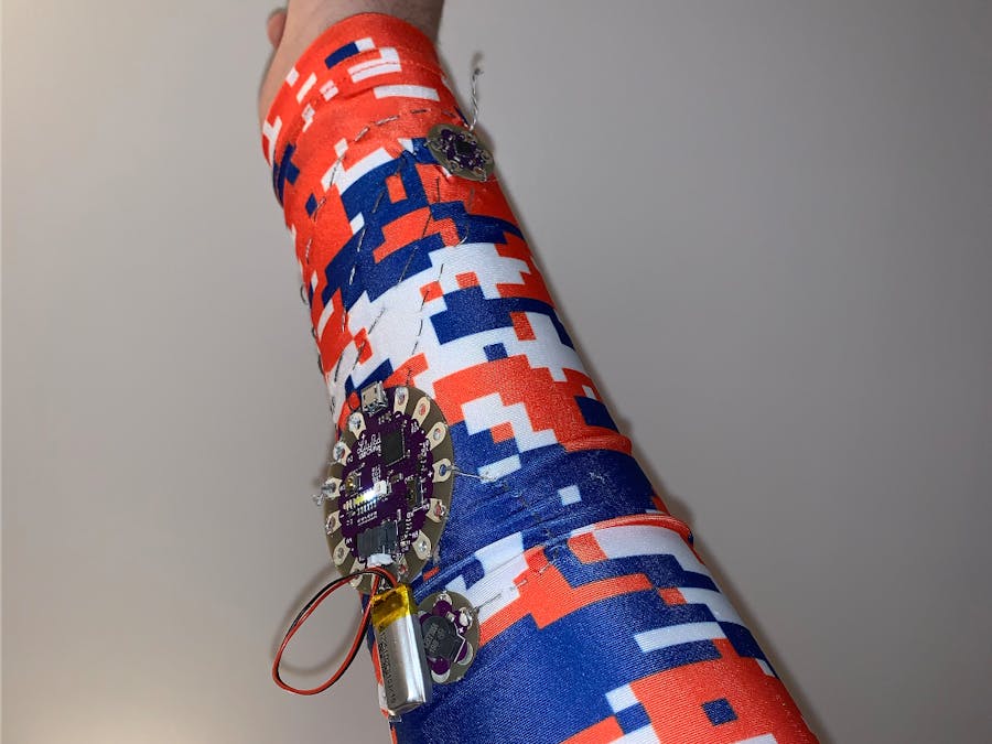
Soldering iron (generic)

Story

Read more

Schematics

Sleeve Schematic

Guideline for laying out circuitry.

Code

Code for Flick Monitoring

Arduino
Had to build out custom code.
// these constants describe the pins. They won't change:
const int groundpin = 18;             // analog input pin 4 -- ground
const int powerpin = 19;              // analog input pin 5 -- voltage
const int xpin = A2;                  // x-axis of the accelerometer
const int ypin = A3;                  // y-axis
const int zpin = A4;                  // z-axis (only on 3-axis models)

// accel range values (change from 0 to whatever you want)
int xLow = 530; // lowest acceptable x accel value
int xHigh = 540; // highest acceptable x accel value

int yLow = 530; // lowest acceptable y accel value
int yHigh = 540; // highest acceptable y accel value

int zLow = 530; // lowest acceptable z accel value
int zHigh = 540; // highest acceptable z accel value

// buzzer values
int buzzer = A9;
int NOTE_C6 = 1047;
int tempo = 100;

// init values
int xVal, yVal, zVal;

void setup() {
  // initialize the serial communications:
  Serial.begin(9600);

  // Provide ground and power by using the analog inputs as normal digital pins.
  // This makes it possible to directly connect the breakout board to the
  // Arduino. If you use the normal 5V and GND pins on the Arduino,
  // you can remove these lines.
  pinMode(groundpin, OUTPUT);
  pinMode(powerpin, OUTPUT);
  digitalWrite(groundpin, LOW);
  digitalWrite(powerpin, HIGH);

// buzzer pinmode setup
  pinMode(buzzer, OUTPUT);
}

void loop() {

  // print the sensor values:
xVal = analogRead(xpin);
  Serial.print(xVal);
  // print a tab between values:
  Serial.print("\t");
yVal = analogRead(xpin);
  Serial.print(yVal);
  // print a tab between values:
  Serial.print("\t");
zVal = analogRead(xpin);
  Serial.print(zVal);
  Serial.println();

if((xVal > xLow && xVal < xHigh) && (yVal > yLow && yVal < yHigh) && (zVal > zLow && zVal < zHigh)){
  tone(buzzer,NOTE_C6);
  delay(tempo);

  // A longer delay at the end pauses the sound before looping again.
  // Here we're delaying four times the "tempo" value:

  noTone(buzzer);
  delay(tempo * 10);
}


  // delay before next reading:
  delay(100);
}

Credits

justin_hiles
0 projects • 0 followers

Comments