


Hardware components | ||||||
| × | 1 | ||||
| × | 1 | ||||
| × | 1 | ||||
| × | 1 | ||||
| × | 1 | ||||
 |
| × | 1 | |||
 |
| × | 1 | |||
Software apps and online services | ||||||
 |
| |||||
I've recently posted a tutorial about this project on YouTube explaining everything you can read on this article. You can watch it right below.
IntroductionHave you ever wondered how to debug your Arduino code or see what your board is actually doing behind the scenes? That’s exactly what the serial monitor is for. It’s a simple but powerful tool that lets you communicate with your Arduino in real time.
This tutorial is lesson #8 in my Arduino for Beginners series, but don’t worry - you can follow along even if you’re just starting out.
And, of course, you can read all the tutorials of this series here.
ExplanationThe Serial Monitor is one of the most essential features of the Arduino environment. With it, you can:
- Display sensor readings directly on your computer.
- Debug logic by printing messages.
- Send commands from your keyboard to control the board.
In other words, if you ever want to know what your Arduino is "thinking", the Serial Monitor is your best friend.
Older versions of the Arduino IDE opened it in a separate window, but with Arduino IDE 2, it’s integrated right into the editor. Even cooler - you can open multiple monitors at the same time if you’re working with more than one sketch.
For this tutorial, I’ll be using the Arduino Cloud IDE.
- Open it in your browser and create a new sketch.
- On the upper-right corner of the screen, look for the Serial Monitor option (see image 1). If it’s grayed out, that means your board isn’t connected yet.
- Plug in your Arduino, reload the page, and wait until the IDE recognizes it (see image 2).
- Now click on Serial Monitor - you’re ready to go (see image 3).
At first it looks like an empty box, but trust me, it gets exciting once you put it into action.
SponsorBefore diving in, a big thank you to DFRobot for sponsoring this series.
If you haven’t heard of them yet, DFRobot is one of the leading companies in the open-source hardware space. They create high-quality, affordable components that are perfect for makers, students, and hobbyists.
For this series, they kindly provided me with the MindPlus Arduino Coding Kit, which includes sensors, modules, cables, and everything a beginner needs to start building meaningful projects.
It’s the kit I’m using throughout the entire course. If you’d like to follow along more easily, check it out.
Thanks again to DFRobot for supporting educational content like this.
Alright, let’s put the Serial Monitor to use with a hands-on project.
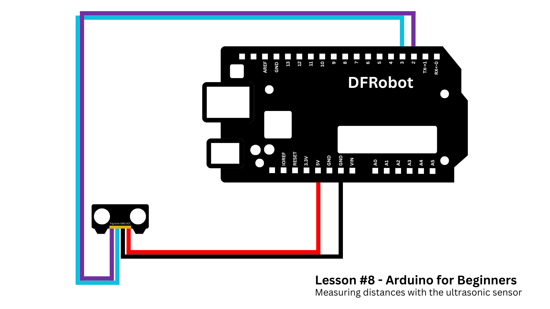
We’re going to connect an ultrasonic sensor to the Arduino and display the distance readings directly on the Serial Monitor.
This will give you a practical idea of how to visualize sensor data and debug your projects in real time.
To accomplish this, follow these steps:
- Plug the ultrasonic sensor into the I/O expansion shield.
- Attach the shield to your Arduino board.
- Copy the code from the GitHub repository of this series and paste it into your sketch.
- Upload the code and open up the serial monitor.
If you need more help setting up everything, you can refer to the schematics below.
Here’s what happens in the code.
First, we defined some variables.
const int trigPin = 2;
const int echoPin = 3;
If you don't know what this means, I recommend you go to lesson 6 in which I explain several coding concepts.
Then on the setup function, we added a new command Serial.begin(9600), as you can see below.
void setup() {
  Serial.begin(9600);

  pinMode(trigPin, OUTPUT);
  pinMode(echoPin, INPUT);
}
This will start the communication between the board and the serial monitor. The number inside parantesis is the baud rate - in other words the speed in which this communication happens. 9600 is the default value.
In the loop function, we're using the ultrasonic sensor to determine the distance of any object close to it.
long duration;
float distanceCm;

digitalWrite(trigPin, LOW);
delayMicroseconds(2);

digitalWrite(trigPin, HIGH);
delayMicroseconds(10);
digitalWrite(trigPin, LOW);

duration = pulseIn(echoPin, HIGH);

distanceCm = duration * 0.0343 / 2;
There's nothing new here. But in the end, we added a bunch of Serial.print() commands.This mean "print a message on the serial monitor."
By the way, the Serial.println() means "print a message and then go to the next line". This way the reading will appear one below the other.
Serial.print("Distance: ");
Serial.print(distanceCm);
Serial.println(" cm");
delay(500);
When you open the Serial Monitor, you’ll see the distance readings scrolling line by line in real time.
If you need help understanding how ultrasonic sensors work, I posted a tutorial about that on my YouTube channel. Don't forget to check it out.
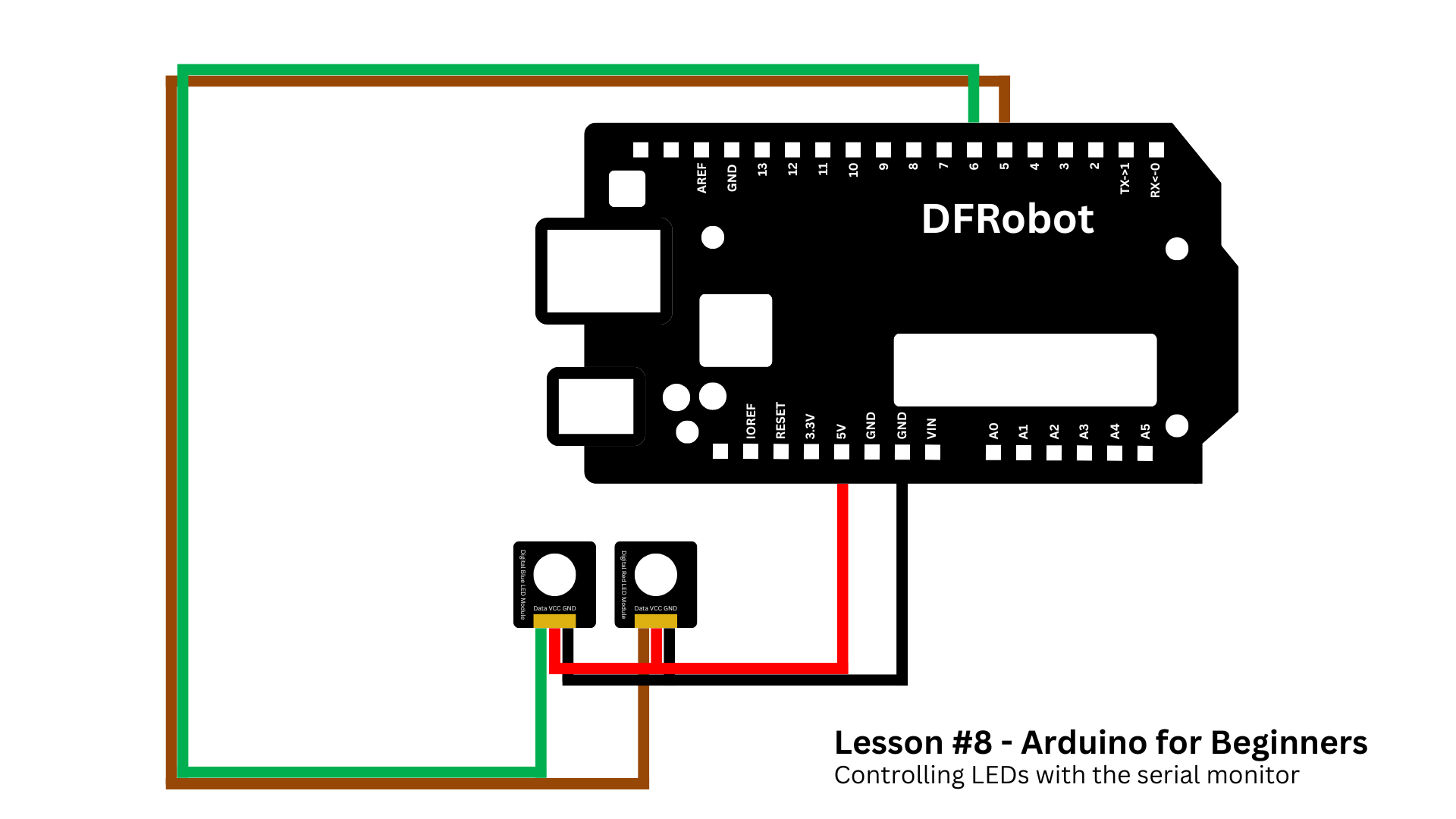
Project 2 - Controlling LEDs Via Serial MonitorNow let’s flip things around. Instead of the Arduino sending data to your computer, we’ll send commands from the Serial Monitor to control LEDs.
So create a new sketch and copy and paste this another script available in today's lesson folder.
This new sketch will allow us to turn on and off two LEDs connected to Arduino by typing words on the Serial Monitor. To accomplish this goal, follow these steps:
- Connect a red LED to pin 5 and a blue LED to pin 6 on the I/O expansion shield.
- Attach the shield to your Arduino board.
- Copy and paste the new sketch.
- Upload the code and open up the serial monitor.
In the serial monitor, there's a typing bar. We can use it to send data to Arduino.
In our case, if you write down LED RED ON, the red LED turns on.
Now if you write LED RED OFF, this turns off the red LED.
You can do the same with the blue LED, by typing LED BLUE ON or LED BLUE OFF.
Now try typing these commands:
- LED BLUE 127 → sets the blue LED to half brightness.
- LED BLUE 255 → full brightness.
- LED BLUE 0 → turns it off completely.
Pretty cool, right? You’re controlling your Arduino with plain text. And as always, here's how this code works.
The beginning and setup function are very similar to the previous sketch, so let's move on and focus on the loop function - the heart of our code.
Inside it, we first check if the user has typed anything into the Serial Monitor using this line:
if (Serial.available())If data is available, we read the full line until the user hits "Enter" and store it in a variable called input.
String input = Serial.readStringUntil('\n');Next, we clean up any extra spaces from the beginning or end of the text:
input.trim();Now, we try to break this input into three parts:
- Command.
- Color.
- Value.
For example, if the user types:
LED RED ON
we want to separate it into:
- LED - the command,
- RED - the color,
- and ON - the value.
To do that, we look for the position of the first and second spaces in the string.
int firstSpace = input.indexOf(' ');
int secondSpace = input.indexOf(' ', firstSpace + 1);
If both spaces are found in the right places, we extract the command, color, and value using the substring() function, and convert them all to uppercase so we can compare them more easily.
String command = input.substring(0, firstSpace);
String color = input.substring(firstSpace + 1, secondSpace);
String value = input.substring(secondSpace + 1);
Now comes the decision-making.
We check if the command is "LED", and if the color is either "RED" or "BLUE". If it is, we figure out which LED pin to use.
if (command == "LED" && (color == "RED" || color == "BLUE")) {
  int ledPin = (color == "RED") ? redLedPin : blueLedPin;
}
Then we look at the value.
- If the user typed "ON", we set the brightness to maximum - 255.
- If he typed "OFF", we set it to 0, turning the LED off.
- If they typed a number between 0 and 255, we use that number to set the brightness level.
We use the analogWrite() function to send that brightness value to the LED pin.
This logic allows us to control LEDs using just plain text, like LED BLUE 150, directly from the Serial Monitor, without pressing any push button.
And that’s it! You’ve just learned how to:
- Use the Serial Monitor to display sensor data.
- Send commands from your computer to control Arduino.
This lesson wraps up Module 2 of the Arduino for Beginners series. Up to this point, we’ve built a solid foundation in electronics and coding. From here on, we’ll start exploring the components inside the MindPlus Arduino Coding Kit, one by one, until lesson 24.
Thanks for following along, and I’ll see you in lesson #9 very soon.


Comments