

Hardware components | ||||||
 |
| × | 1 | |||
Software apps and online services | ||||||
| ||||||
This project is just one piece in what will hopefully become a series of what I am calling "DarnedCircuits". These are broken electronic devices that I have been "fixed" with textile mending techniques. They don't work the way they originally did, but their interactive nature gives them a new life. Specifically, I target electronic devices that are tied in function to productivity and transform them into objects that cannot be used to produce anything beyond amusement. Instead of representing production and progress, they become useless jokes that incorporate pieces discarded items from some of the two most wasteful individual consumer industries: clothing and electronics, to call out our relationship with production, consumption, and waste. These absurd objects mirror the absurdity of the waste-replace cycle that we have normalized in our lives through fast fashion and ever-changing electronics trends.
BackgroundIn a previous project, I had made a small patch using a mending technique called ‘darning’ which involves weaving threads back and forth over the hole in cloth to essentially create a new fabric. I used this technique, some copper tape, Velostat (a piezoresistive sheet), and conductive thread to turn this patch into a pressure sensor. In my first version, before the mended laptop project really began, I connected the conductive thread to some LEDs which would visualize the pressure applied to the patch by varying the brightness.
For this laptop project, I decided to use the same technique to make a ‘trackpad’ which could create reactions on the ‘screen’ such as lighting LEDs as well as playing audio. The idea is to keep the familiar muscle memory people have of how to interact with a laptop so that it becomes clear how to make a reaction happen.
This project and documentation is from the MDEFest Challenge which is a part of the Master in Design for Emergent Futures course from the Institute for Advanced Architecture of Catalonia, Elisava, and Fab Lab Barcelona. For this challenge, we were prototyping artifacts to use during the festival culmination of our program. Some of the work on this project was done before the start of the challenge week which was 3.5 days of prototyping time.
ProcessTools
- Screwdriver(s) - various sizes and types, dependent on the screws in the device you are taking apart
- Sewing Needle
- Scissors
- Soldering Iron
- Multimeter
Materials
- Conductive Thread
- Velostat
- Copper Tape
- Fabric
- Embroidery floss or thick thread
- Metal snaps
- Resistors - various around 100-330Ohms
- LEDs
- MCP3008 8 Channel ADC
- Breadboard and jumper wires
- Speaker and any associated hardware - amplifier might be useful
- Raspberry Pi Pico
- An Old Laptop
Before the Challenge started, I disassembled the laptop and took stock of what I had and worked on figuring out what I wanted to use for the final mended laptop. This process involved discovering what is inside a laptop in a way that we often do not get to see. There are many potentially useful parts within the laptop and if you are repeating this process, I suggest making careful notes of what everything is, where it goes, make sure to save the screws, ideally separated and labeled. You never know what you will want to use when you reassemble.
For this project, I will primarily use the plastic and metal pieces of the laptop and will mostly not use the electronics from the broken device. Although the goal of this project was to use as much reused material as possible and to ‘repair’ the laptop, the challenge to use existing hardware that I do not have a datasheet for nor knowledge of whether certain pieces function or not, with the limited time, it made sense to use the physical case of the laptop while mostly admitting that new electronics are needed.
Create the TrackpadAlso before the Challenge started, I made the trackpad itself. This took around 15 hours of weaving the threads and constantly readjusting, trying to make sure that the Velostat fully covered the copper pad on the bottom, and that the conductive thread did not cross.
The Circuit
The process of weaving the trackpad is slow, tedious, and requires a lot of patience. Getting the tension right, not pulling too much, not letting the threads bunch up, and constantly adjusting is important.
I started taping the copper pad down to the fabric and making sure to have a piece of conductive thread attached so that you will be able to access this later once the weaving has covered everything.
Then I laid the Velostat on top, making sure it could fully cover the edges of the copper. You will want to check that the piezoresistive layer is bigger on all sides than the copper pad. I made this mistake and had to make many adjustments later which made the whole process take longer.
Before weaving, I attached the Velostat to the jeans with a post-it note on either side so that it wouldn’t move around.
In the case of this weaving, since I wanted the conductive thread to run up and down through the trackpad, I started with the warp of the weave going across the width of the trackpad.
After completing the warp, I began the actual weaving. For the conductive thread, I had it go only part way through the weave so that there would be a top and bottom to the trackpad to make it more like a normal trackpad. To do this, I looped the conductive thread around one of the middle warp lines and then wove both ends of the thread through the warp.
Were I to do this again, I would not do the weaving on the fabric itself and I would keep the ends much longer so that adjustments can be made. If you plan to duplicate this process, I suggest weaving on a loom, leaving the ends of the threads (both warp and weft) long. Then you will be able to sew your patch onto the fabric. This is not how darning is traditionally done, however given the complication of the copper layer and the Velostat, it would have been helpful to have the pieces separate so that I could make sure all of the layers were aligned correctly without having to constantly take things out, readjust, and try again.
Throughout the process, use your multimeter to check that the conductive thread is not shorted with any of the other threads or the copper plate on the bottom. This would also be easier if the weaving were done separate from the fabric itself.
Connect the TrackpadFirst Attempt
At the start of the Challenge, with the trackpad mostly completed, it was time to test it. To do this, I attached the conductive thread to wires by sewing the thread around a piece of the wire.
Unfortunately, this did not last very long, the wires were snapping and the connections seemed temperamental. So, after spending many hours trying to change the trackpad itself to accommodate the differences in resistivity of the different strands, I decided I needed a new approach.
Second Attempt
If you are replicating this project, I suggest skipping the first attempt and moving right to this version with the snaps.
- Sew one side of the snaps onto your fabric using the conductive thread.
- Check the connectivity to make sure you have successfully created an electrical connection.
- Solder the other piece of the snap to the wire you want to use.
- Make sure the snap still works, that the solder has not interfered with the sprung part of the snap.
Suggestion(that is opposite of what I did): Sew the part of the snap that has the ‘sprung’ part. This piece could be referred to as the ‘in’ part of the snap so that the solder does not mess with the movement portion of the snap. I did this the other way because I wanted to wrap the wire inside the cavity in the snap, but in hindsight, the other way may have been better. Either way, use your multimeter to make sure you have established connectivity and that the connection is strong enough to not break.
To visualize the connections, attach the LEDs and start testing the pressure sensor inputs.
If some of the LEDs seem dimmer than others, you can experiment with different resistor values. However, the reality is that the Velostat may not be uniform across the whole piece, the tightness of the weave may change how much contact the thread has with the pressure sensor, and many other factors that I have yet to explore.
This is the piece of the project that probably was the most infuriating because it was unclear how to make it more consistent. This is still a work in progress, still a prototype and an experiment.
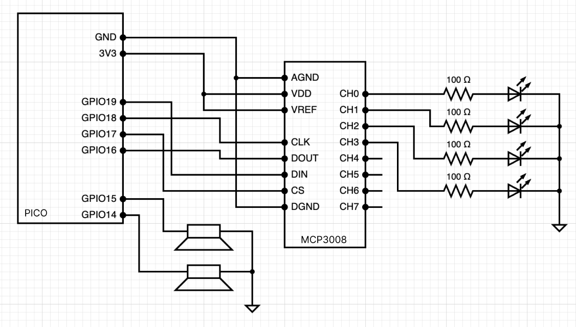
Once the LEDs were hooked up, I attached some of the pins to the MCP3008 chip. This is an 8-channel Analog to Digital Converter with SPI interface which will allow me to read the analog voltage from the touchpad into the Pico so that I can have a digital response instead of only having the LED brightness analog response. The Raspberry Pi Pico has only 3 ADCs built-in, so the MCP3008 allows for expanding this to 11 total for the setup.
Prior to the Challenge beginning, I had been working on a python class for this project. It is still a work in progress and I hope to update the documentation going forward as well, but you can find the code on the linked GitHub.
The values I was reading in from the ADC were pretty inconsistent which made setting a threshold very challenging. This is something I will have to address going forward. I wanted the ADC channels to control the audio output, so I also hooked up the speakers from the original laptop.
Another approach I tried was to look for the change in the value such that I could compare the changed values rather than relying on a single reading. This somewhat worked how I wanted for the audio output, but did not work as well as I had hoped. More work will need to be done on this.
from machine import Pin, PWM
from mcp3008 import MCP3008
from time import sleep

# ------------- setup the MCP3008 -------------
# constants - set the MCP3008 pins
SCK_PIN = Pin(18
MOSI_PIN = Pin(19)
MISO_PIN = Pin(16)
CS_PIN = Pin(17, Pin.OUT)

spi = machine.SPI(0, sck=SCK_PIN, mosi=MOSI_PIN, miso=MISO_PIN, baudrate=100000)
cs = CS_PIN

# create the MCP3008 instance
chip = MCP3008(spi, cs)

# ------------- setup the PWM Speakers -------------
# constants - set the PWM pins
SPEAKER_LEFT = PWM(Pin(14))
SPEAKER_RIGHT = PWM(Pin(15))


if __name__ == "__main__":
    THRESHOLD = 500
    adc_chs = [0, 1, 2, 3]
    pressed_lst = [0, 0, 0, 0]
    note_freq = [440, 523, 587, 659

    try:
        while True:
            for ch in adc_chs:
                pressure = chip.read(ch)
                print(f"Pressure: {pressure}, on Channel: {ch}")
                if (pressure > THRESHOLD):
                    pressed_lst[ch] = 1
                else:
                    pressed_lst[ch] = 0

            all_off = not any(pressed_lst)

            if all_off:
                SPEAKER_LEFT.duty_u16(0)
                SPEAKER_RIGHT.duty_u16(0)
            else:
                SPEAKER_LEFT.duty_u16(int(65535/2))
                SPEAKER_RIGHT.duty_u16(int(65535/2))

            for i, sound in enumerate(pressed_lst):
                if sound:

                    SPEAKER_LEFT.freq(note_freq[i])
                    SPEAKER_RIGHT.freq(note_freq[i])

    except KeyboardInterrupt:
        SPEAKER_LEFT.duty_u16(0)
        SPEAKER_RIGHT.duty_u16(0)
This piece of the project is still in process and will likely evolve as I finish securing the fabric to the laptop body itself once and for all.
HingeOn the laptop I was attempting to repair, the hinge for one side of the screen was broken, so I wanted to try to fix that so that it could still function as a laptop, with the ability to close.
had to reattach the threaded inserts into the plastic of the screen case. Initially I CADed a piece I could 3D print and glue in place, but realized it wouldn’t allow the hinge to turn as I needed it to and decided to just superglue the inserts into the case.
In the spirit of trying to use mostly discarded material, I found a piece of metal and started shaping it by hand to fit it into the space it needed to fit to secure the screen to the main body.
In the process of reforming the attachment for the hinge, I realized I had to use different screws to attach the hinge to the case. Unfortunately, the screws I had from before were not long enough with my new setup. When I tried using another set of screws, they caused some poblems with closing as well. This is still something I need to work out and figure out.
The goal was to complete this project by the end of the challenge, however, as so often happens, more challenges came up along the way than I had anticipated and everything took longer than I had hoped.
Going forward, I need to get the hinge working correctly so that the laptop can open and close. I also need to attach the fabric to the case, create a ‘screen’, create a more permanent setup with the electronics, finish documenting the code, and put the laptop housing back together.
There is still a lot of work to do on this and I hope to get it done before the MDEFestival.
In terms of visible mending practices, there are so many references to choose from, however most personally, the work of both my own mother and that of Penny Papachristodoulou come to mind.
The trackpad itself comes from the practice of darning used primarily to fix socks.
I was inspired by the soft sensor made in the class we had as part of our program that was taught by Citlali Hernández which I wrote about in a previous project.
Some more references I used for integrating electronics with textiles are various tutorial websites that gave me ideas about what is possible.
- https://www.kobakant.at/DIY/
- https://class.textile-academy.org/tutorials/#electronics
- https://beckystern.com/2021/02/26/zodiac-embroidery/
- https://class.textile-academy.org/2020/carolina.delgado/assignments/week05/
In terms of the idea itself, to embrace the oddity and lack of traditional functionality of this laptop 'mend' I was somewhat inspired by the work on maker Simone Giertz, specifically in her TED Talk titled "Why you should make useless things". Additionally, the work we did during the Machine Paradox class as part of our program provided a lot of the inspiration.
Cognitive Contribution License (CCL)One of the faculty at Fab Lab Barcelona has created a simple tool for declaring how much AI contributed to your project. This represents the amount of AI used in the project which was very minimal. There was one moment where I was getting assistance from one of our teachers and he asked ChatGPT how it would produce the logic we wanted in the code. However, most of this project is completely my own work. My CCL for this project can be seen below.


Comments