Whether bought or built, touch sensors react to the electrostatic charge of humans and put them into a switching signal. You're probably wondering why you can not switch ordinary transistors or microcontrollers by touch - would that be a great thing, right?
Well, it's not that easy. In the "normal" state all electrical potentials are balanced, and our circuit would not work. Now the friction comes into play: Between your T-shirt and the jeans, the sweater or the floor and your shoes. Sometimes, when you are heavily electrostatically charged, you get a "wiping" when touching metal objects (doorknob, car, heater) - the potential is reduced or equalized in a spark.
However, our small circuit does not need such a high charge because it uses transistors for signal amplification.
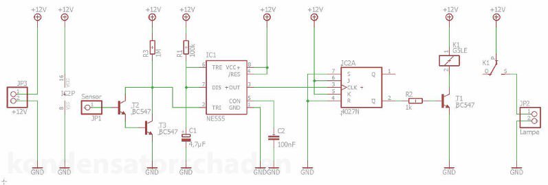
The circuit:
The metallic body of the lamp serves as an antenna - the larger the surface, the more potential is absorbed and the lower the gain must be. It consists of up to two BC547 NPN transistors, which amplify the voltage at the input, as the lamp body you touch, by a factor of 10,000. Thus, a very low, not noticeable charge enough to turn the lamp safely on and off.
Thus, despite the minimum potential of the body, we reliably achieve the switching voltage of about 0.7V at the input of the flip-flop, which then turns on the relay and thus lights the lamp.
This would clarify the mystery of the magical switching operations of our circuit, but what is the purpose of timer NE555?
Well, the flip flop together with the amplifier circuit would switch our lamp on and off so fast with every touch that it would be a coincidence if the lamp remained in the desired state - with the NE555 and a simple resonant circuit we can use a capacitor and a resistor, the minimum runtime define that lies between two switching cycles. Only when the capacitor is fully charged can a new cycle begin and the flip-flop switch the lamp again.
The circuit is therefore reduced to the most necessary components, constructed completely analog and easy to copy. With such a small 1.7 watt LED as we used, you could possibly replace the relay with a stronger power transistor, but with the print relay you are always on the safe side. The circuit operates with an operating voltage of 5 to 12 volts, whereby in our layout the input voltage is also the supply voltage of the LED behind the relay. Therefore, the choice fell on a 12 volt LED and a small switching power supply, which supplies the circuit as well as the lamp at the same time with voltage. Depending on the consumer, it is also possible to operate using a 9V block or another type of battery (button cells, lead acid batteries).
For the replica you do not need a deeper understanding of the circuit. A breadboard, a soldering iron, and a little stranded wire are the only ingredients you need next to the circuit components.


Comments