

Hardware components | ||||||
 |
| × | 1 | |||
 |
| × | 1 | |||
Software apps and online services | ||||||
 |
| |||||
| ||||||
Hand tools and fabrication machines | ||||||
 |
| |||||
The desire to have a portable TTL serial monitor has been at high level when I started this project. Many times as programmers we need one, small & portable for debugging on-the-field in special conditions where we cannot have a computer with a monitor.
Here it is a complete serial monitor, works at different speeds, with a clear screen button and a pause button to stop scrolling data; last but not least I added special functionality to get attention in special situations when debugging: playing a "bip" and changing "colour" of the text to yellow, green, red, cyan, or white the original colour, just adding simple control codes to your Serial.print() commands.
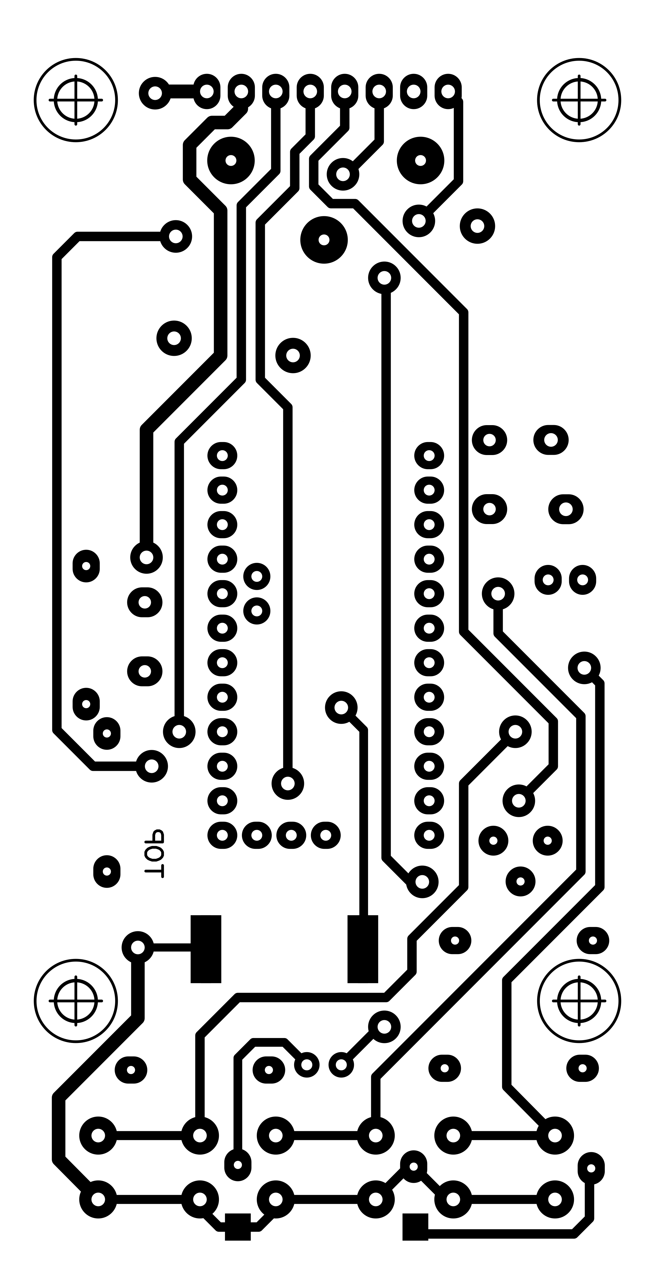
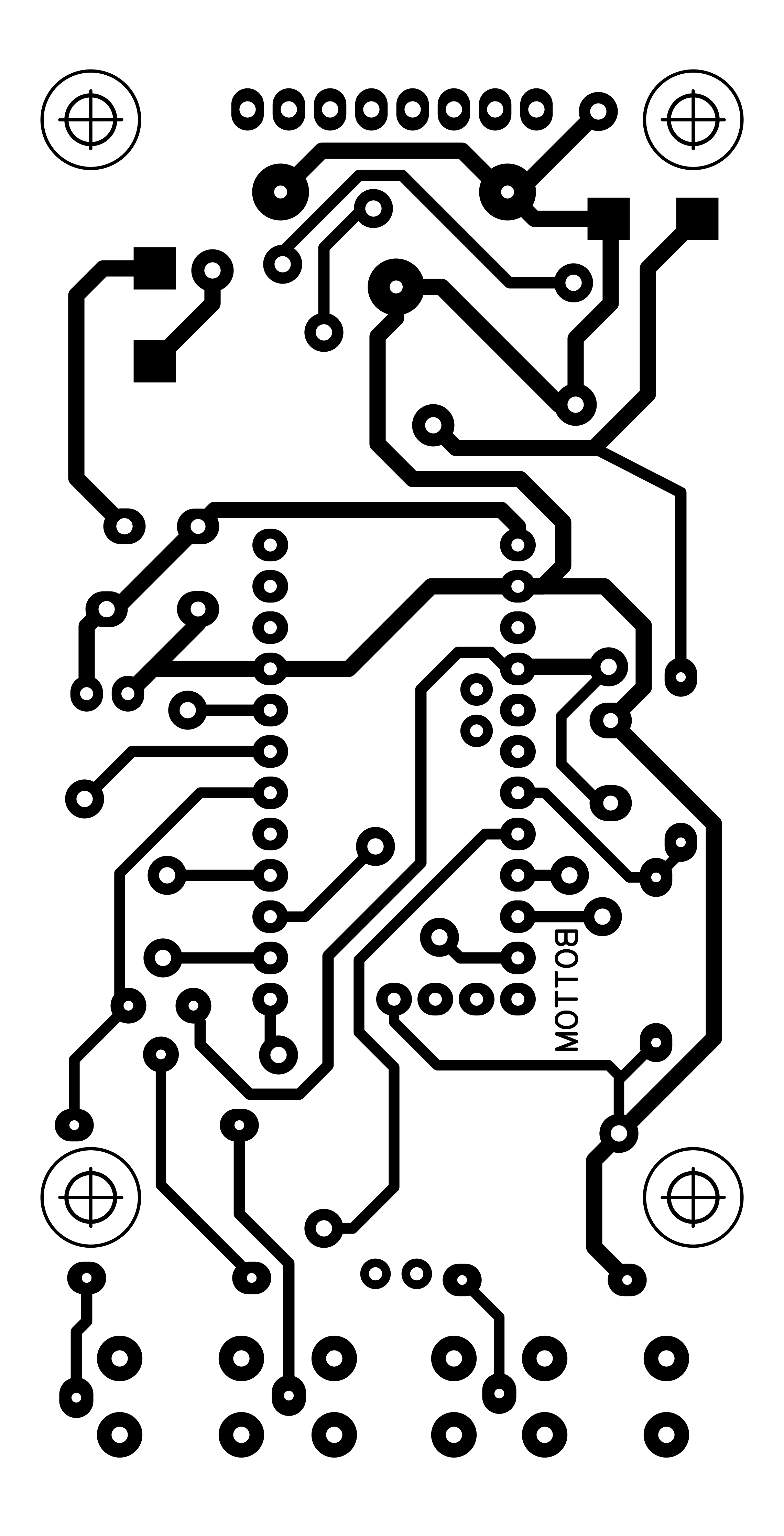
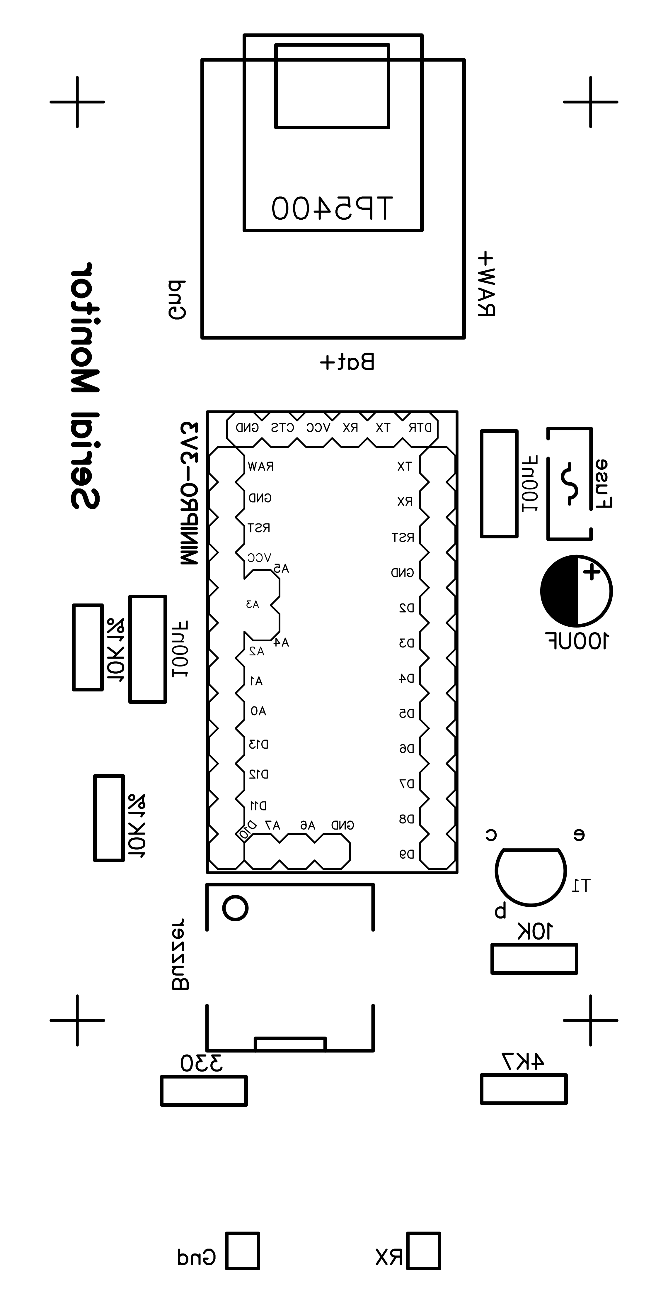
The MCU is an Arduino MiniPro 3.3V, the display is an ILI9341 2.4" 240x320 RGB (blue model) with SPI interface, in portrait, with scrolling functionality thanks to a modified library. A passive buzzer will provide the sounds, a TP5400 module provide both recharging the Li-Ion 1A/h 3.7V battery and step-up to 5V to power the MCU on RAW pin and use its internal 3.3V regulator.
The Arduino internal voltage regulator limit is 150mA of current, but actually the whole circuit needs just around 65mA; to recharge let connect a micro-USB cable; the USB-A female is for powering an ipotetic additional equipment with 5Vcc needs, i.e. the circuit to monitor;
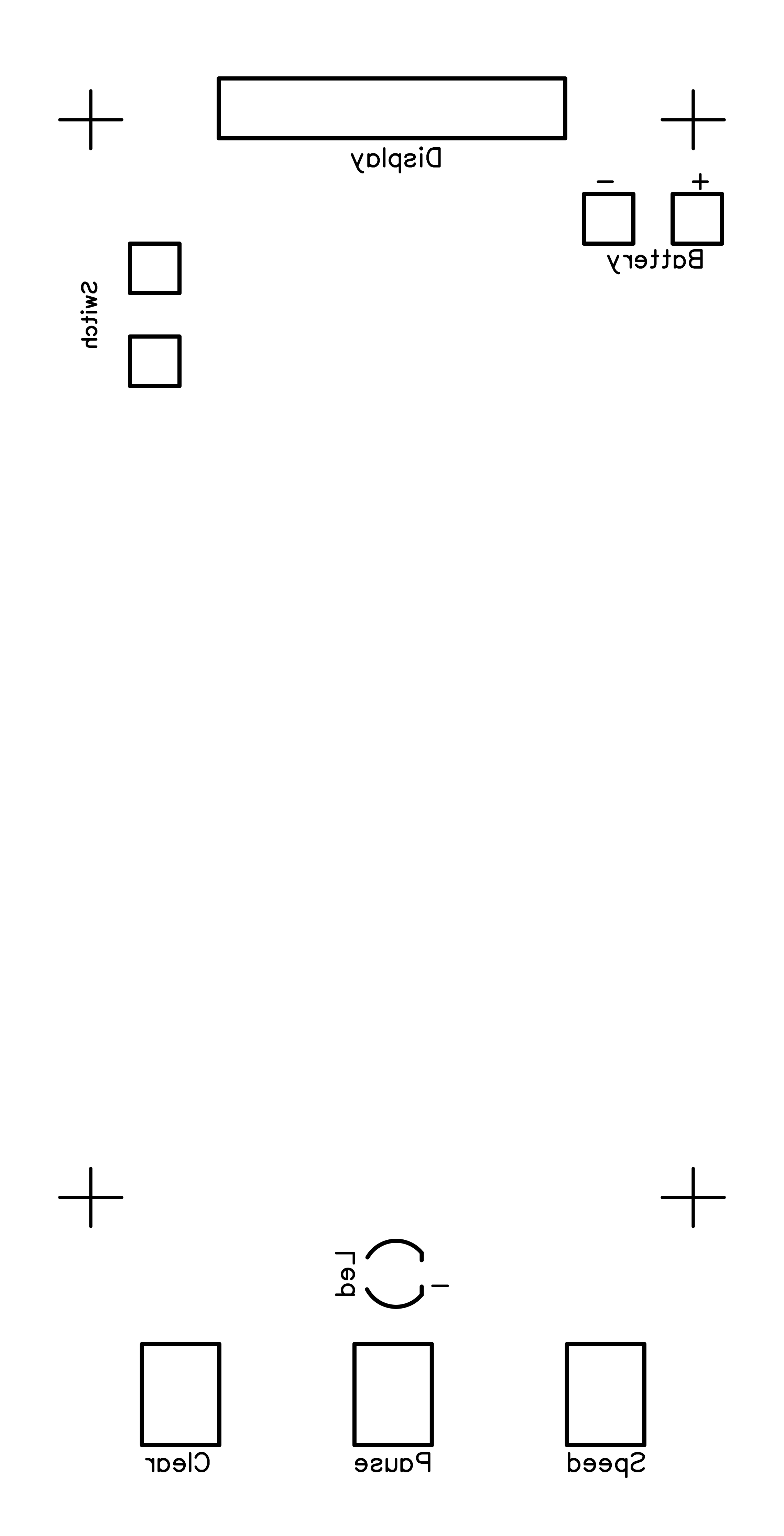
The circuit works at 3.3V. The input can be a TTL logic level from 0V to between 3-5V and some more if really necessary because R2=4.7K, R3=10k and Q1=BC337 will control the signal for the MCU input port. R4 and R5 are used as voltage divider to measure the battery voltage, buzzer will warn you when recharging is needed. The red LED lights up when Pause button is pressed; in pause mode the data stop scrolling and the buffer is emptied. Another button is for Clear the screen, and the last one is for changing the desired speed (300, 1200, 2400, 4800, 9600, 19200 and 38400).
As usual, to transfer the sketch to the Arduino Mini Pro you need a FTDI (USB to serial) module set at 3.3V.
- Arduino Mini Pro 3.3V
- Display ILI9341 2.4" TFT-LCD 240x320 RGB (blue model), SPI interface
- TP5400 recharging and step-up module (see pictures)
- Li-Ion 3.7V 1A/h rechargeable battery
- 2 x 10k resistors (possibly 1% and selected to be similar as value)
- 1 x 4.7K resistor
- 1 x 10k resistor
- 1 x 330 resistor
- 2 x 100n capacitor
- 1 x 100uF 16V electrolytic capacitor
- 1 x self resettable fuse 200mA
- 1 x mini switch to on/off
- 1 x 3mm red LED
- 3 x mini tactile push buttons 13mm high + 3 x black caps
- 1 x passive 3.3V SMD buzzer (12x12mm)
- 1 x BC337 NPN transistor
- 2 x female 2mm panel plugs (black and red)
- 3D printed box + cover
- 1 x PCB connector 8 pin, male and female (display)
- 8 x 3mm spacers
- 8 x 3mm screws
on your equipment to monitor you may add some control characters in your debug code messages to enrich/simplify the debugging: in this way you may change text colour on the display and play a sound when you like just adding one of these control-codes when necessary:
- CTRL-A, ASCII=01 (start YELLOW)
- CTRL-B, ASCII=02 (start GREEN)
- CTRL-C, ASCII=03 (start RED)
- CTRL-D, ASCII=04 (start CYAN)
- CTRL-E, ASCII=05 (start WHITE, recover the normal colour)
- CTRL-G, ASCII=07 (play a bip)
As example:
char ccBEL=07;
Serial.print(ccBEL);  // you will have a "bip" sound on the serial monitor
char ccRED=03;
char ccWHITE=05;
Serial.print(ccRED);
Serial.println("Warning: out of range!");  // you will have a red colour message on the external serial monitor
Serial.print(ccWHITE); // recover the normal white colourdefault speed is 9600 with 8 bit, NO parity, 1 stop (SERIAL_8N1) but with speed button you may change to 300, 1200, 2400, 4800, 9600, 19200, 38400 baud; I tested a continuous RX works up to 4800; higher speed could make the buffer full during continuous receiving because display is slower then receiving data; occasional RX data as per usual serial monitor purposes of debugging will works fine even with higher speeds;
To avoid interferences during uploading the sketch, I used 2 new pins for serial RX/TX by the way of SoftwareSerial library, so the communication pins are 4 and 5;
Are displayed only printable characters in the ASCII range 32-126, so no control codes and no extended ASCII are show (all ignored);
In Pause mode the display stops to show more data, so the receiving data is ignored (lost);
Looking at TP5400 module data-sheet they say it will charge at 900mA current because the programming resistor installed on pin 3 of the chip is a 1.2k Ohm; the Li-Ion battery I used for this project has 1450mA/h so in around 1.5h is charged; I think the charging current in this case is adequate even if I usually like a less charging current comparing to the battery capacity; just to warn you to avoid to install a smaller capacity battery, or you should change the resistor to a bigger value (10k -> 130mA, 5.1k -> 245mA, 2k 560mA, 1.5k -> 740mA, 1.1k -> 1000mA); i.e. for small 350mA/h battery I suggest to change pin 3 programming resistor to a value between 5.1k and 10k Ohm.
Every 30" the software checks battery voltage: if less than 3.4v it generates a sound as warning to provide to recharge the battery soon; full battery should last around 15h.
The SoftwareSerial library buffer size is 64 bytes; I modified SoftwareSerial.h and SoftwareSerial.cpp to 512 bytes, so now is more difficult to make the buffer full; for a more comfortable use you should modify the library too as per instructions and pictures; this sketch use around 1450bytes of memory plus the 512bytes of the enlarged buffer it should stay below the 2kbytes limit of Arduino Mini-Pro.
you have to download and install the customized "_AS" libraries for the display to allow scrolling written by Alan Senior 15th February 2015:
#include <Adafruit_GFX_AS.h>     // Core graphics library customized by Alan Senior
#include <Adafruit_ILI9341_AS.h> // Hardware-specific library customized by Alan SeniorTo keep in place the TP5400 recharging and step-up module you have to solder three strong pins on the USB-A connector chassis, and aligning them with the three spots on the PCB.
Pay attention to take care the delicate flat cables of the display specially in proximity of the 4 holes for the screws or the spacers.
PCBWay Services:Even this time I decided to try the famous and popular PCBWay services. Some our beautiful project deserve a real professional service giving to them precise and superb items like PCB and 3D enclosure/component. I visited for the first time PCBWay website last year (http://www.pcbway.com) and after a few minutes I had been able to obtain the final price of the PCB just uploading the.ZIP Gerber file and setting some preferences of the board like colour: I choosen the red but is still available the most popular green, or a shining white, blue or others. They shown to me a preview of the board: impressive.
The same for the 3D printings (just uploading the.STEP or .STLfile/s) and you cannot image how many materials are available: PLA, ABS, PETG, Resin, Polycarbonate but as well as Aluminium or Steel or... Titanium! What, Titanium?! It is incredible.
They offer other services actually I have not tried them yet but with these two I can say I am very satisfied. Shipping time were quick. The price was adequate. The customer care office and technician production office demonstrated to me to be ready and "sharp" for details.
News / Updates:- 12.05.2025 - 3D printing models: I just published even on GrabCAD website the 3D parts you may print for this project.
- 13.05.2025 - If you wish I have a few PCB from PCBWay ready to solder the components on, I can send to you one if still available: first come first served.
Enjoy the project! :-)


_3u05Tpwasz.png?auto=compress%2Cformat&w=40&h=40&fit=fillmax&bg=fff&dpr=2)
Comments