

Hardware components | ||||||
| × | 1 | ||||
Software apps and online services | ||||||
 |
| |||||
| ||||||
Hand tools and fabrication machines | ||||||
 |
| |||||
as aviator pilot it is important on the air and on the ground to keep the "Safety First" in many aspects of the flight and pre-flight, one of these is avoiding collisions. Last few years even small aviation, free-flying aircrafts as per sailplanes, paragliders, hanggliders, etc., in future drones too, started to adopt instruments to see and let be seen to others. The sky will be crowd.
One cheap but effective instrument is the T-Echo model of LilyGo company. The T-Echo can be used installing various software, my favourite one is SoftRF version by M.Braner. SoftRF has been originally made by Linar Yusupov but some others decided to modify / improve his project.
How it Works:When you are airborne T-Echo transmit and receive to/from other flying aircrafts radio digital data containing informations regarding altitude, speed, direction, etc. ; is needed and very important that you and other aircrafts around using the same communication protocol or NO CORRECT or NO WARNINGS are exchanged!
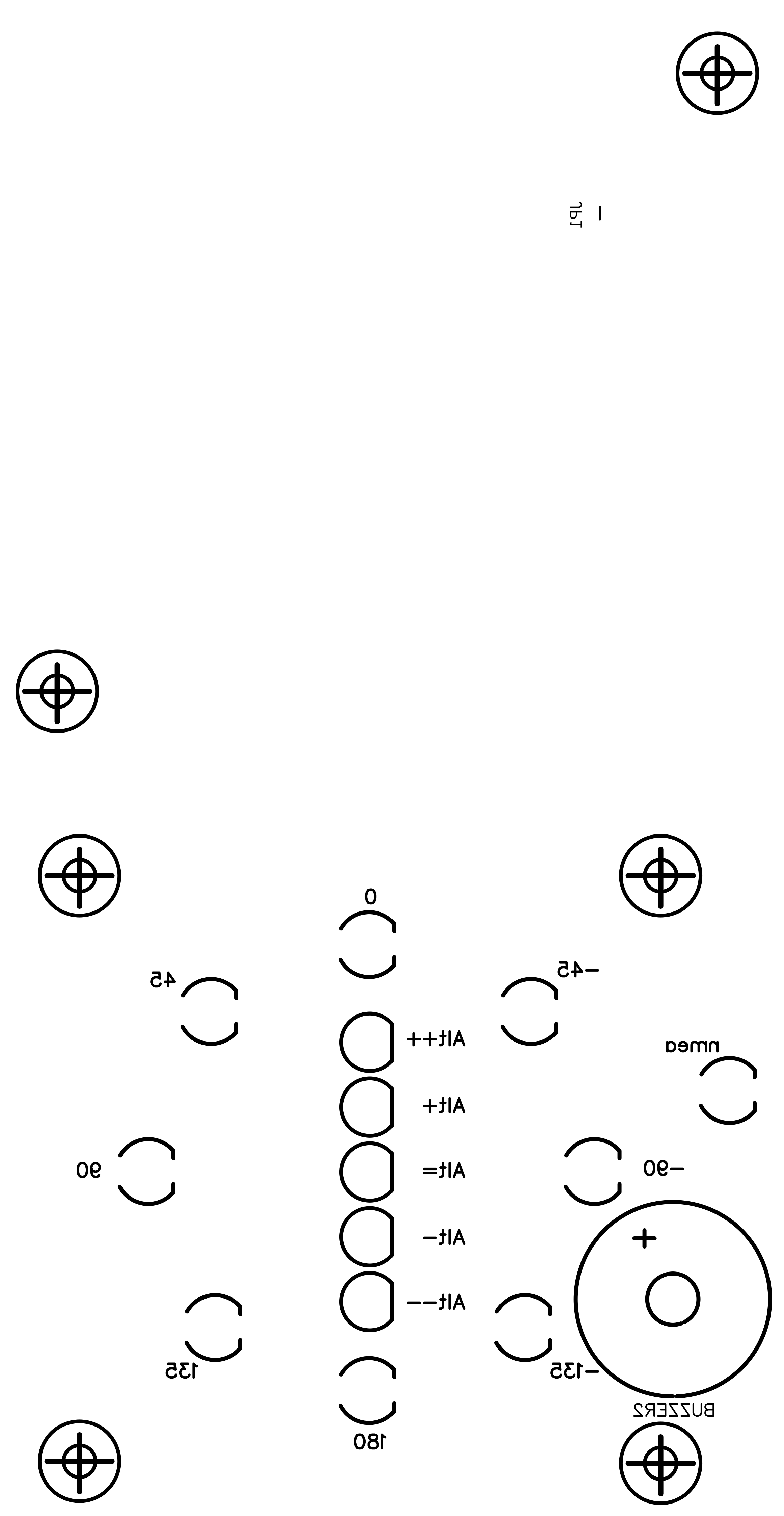
If correct data is received and a possible collision is detected by T-Echo, it transmits via bluetooth, and received by this circuit, the relative NMEA sentence warning: 1 of the 8 directional blue LEDs will indicate to you the relative position of the detected aircraft (upper LED at 12:00 o'clock means it is straight ahead, right LED at 03:00 o'clock it means it is around 90° at your right, lower LED at 06:00 o'clock means it is behind you, etc.). Additionally 1 of 5 altitude LEDs will indicate to you the relative altitude of the aircraft: middle red LED means the aircraft is between -50 +50 meters altitude from you, yellow LED means between +-51 +-150m, green LED means the aircraft is over or below of you more than +- 151m (please apply the mods on code suggested in News/Updates section).
This project makes bluetooth-LE connection with LilyGo T-Echo + SoftRF (Moshe Braner version MB158); the sketch, with the LED Indicator Circuit, connects T-Echo for receiving NMEA collision warnings sentences via bluetooth-LE, evaluates the warning/s level and produces "bip" sounds with a buzzer (3 levels); additionally it shows on 1 of 8 LEDs the relative direction and on 1 of 5 LEDs the relative altitude of the potential collisioning aircraft; there is also a status LED to show NMEA activity;
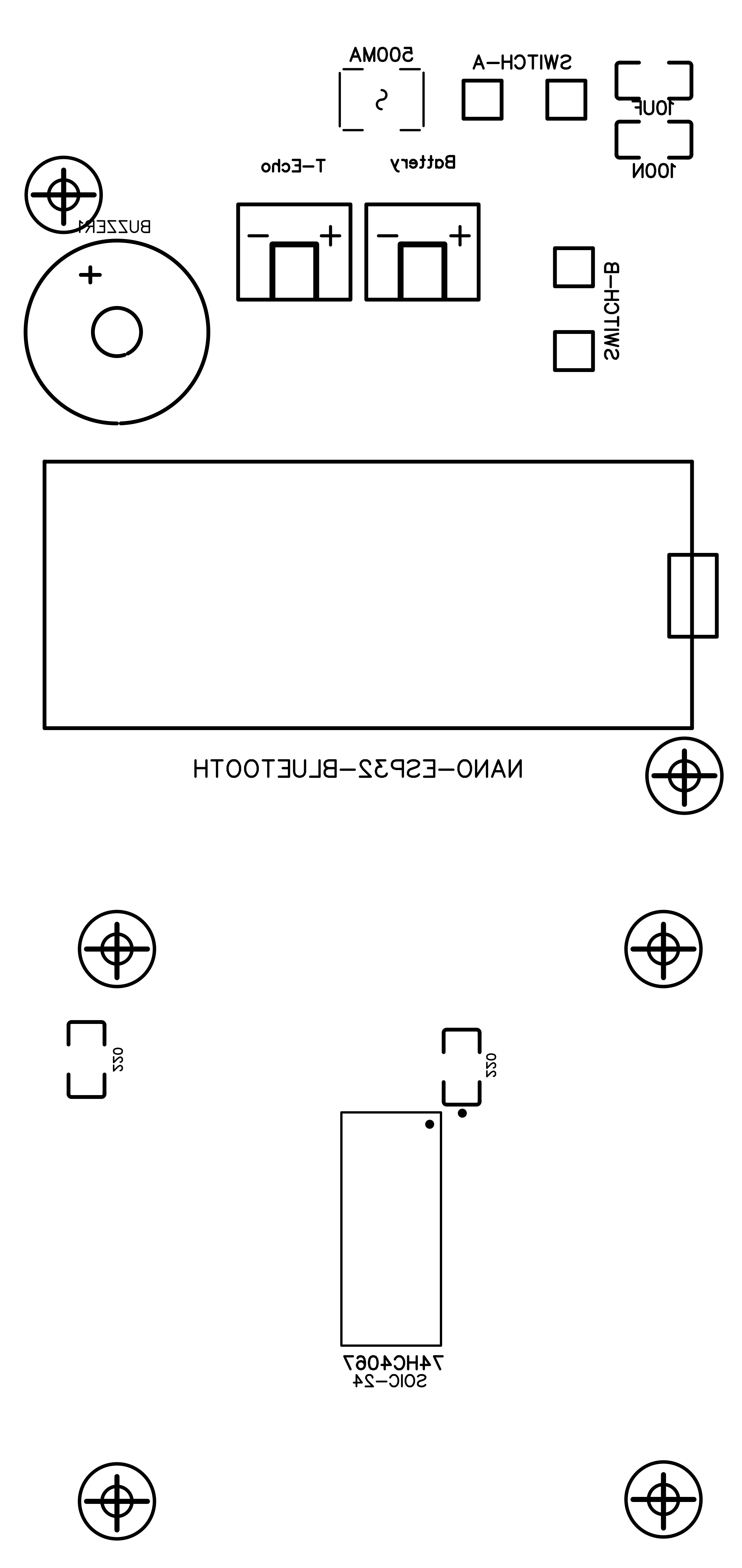
- Arduino Nano ESP32, MCU with bluetooth BLE, 3.3V
- IC 74HC4067 version SOIC-24, 16 channels multiplexer SMD
- Active Buzzer 3.3V
- 2 x 220 ohm SMD resistor (size 1206)
- 1 x 100nF SMD capacitor (size 1206)
- 1 x 10uF SMD capacitor (size 1206)
- 8 x 3mm LED blue
- 1 x 3mm LED red
- 3 x 3mm LED green
- 2 x 3mm LED yellow
- 2 x JST-XH 2.5mm connectors (90° male, straight female)
- 1 x 500mA self resettable fuse SMD
- 2 x mini switch
- Li-Ion 3.7V 2100mA/h battery
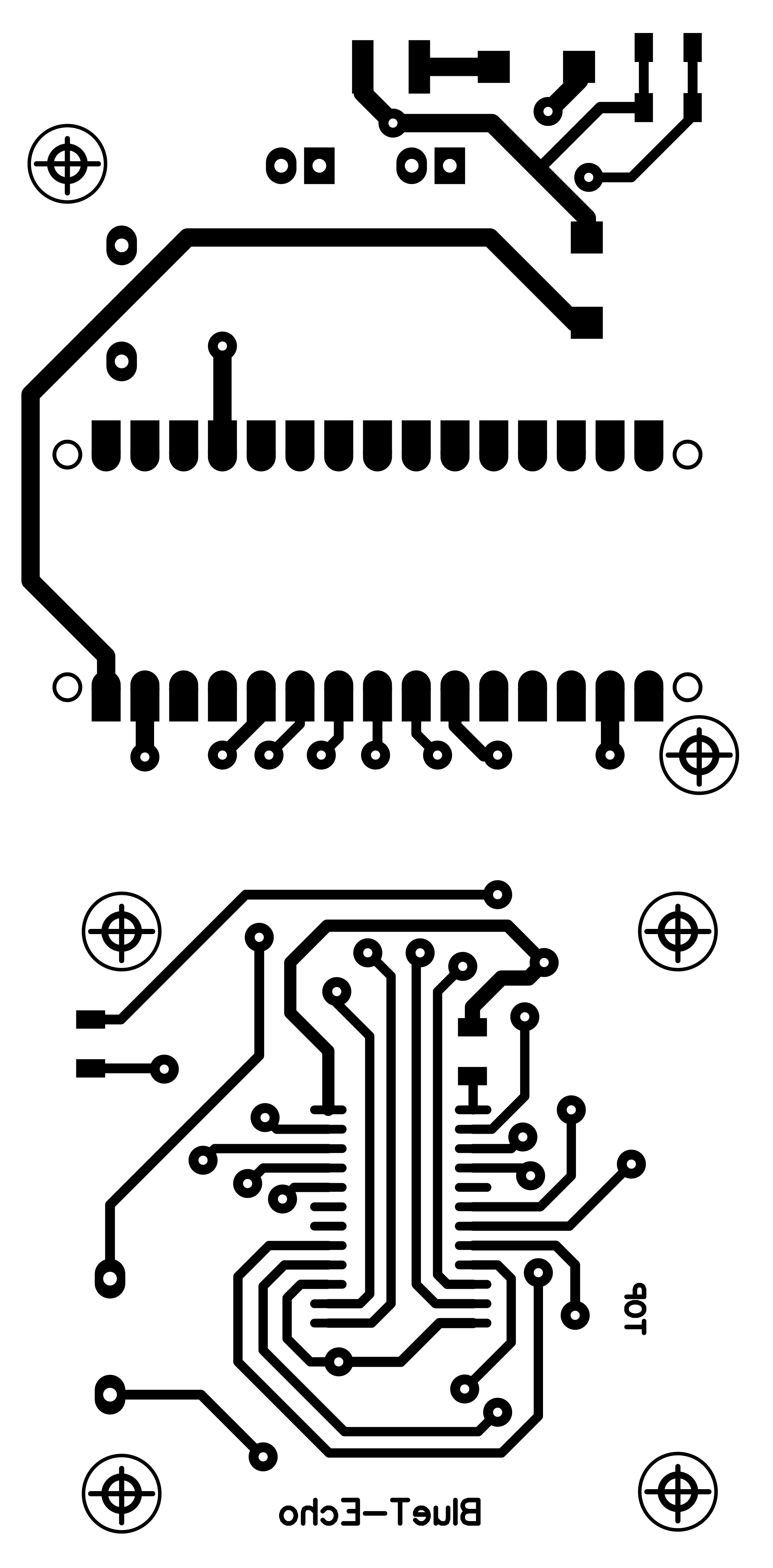
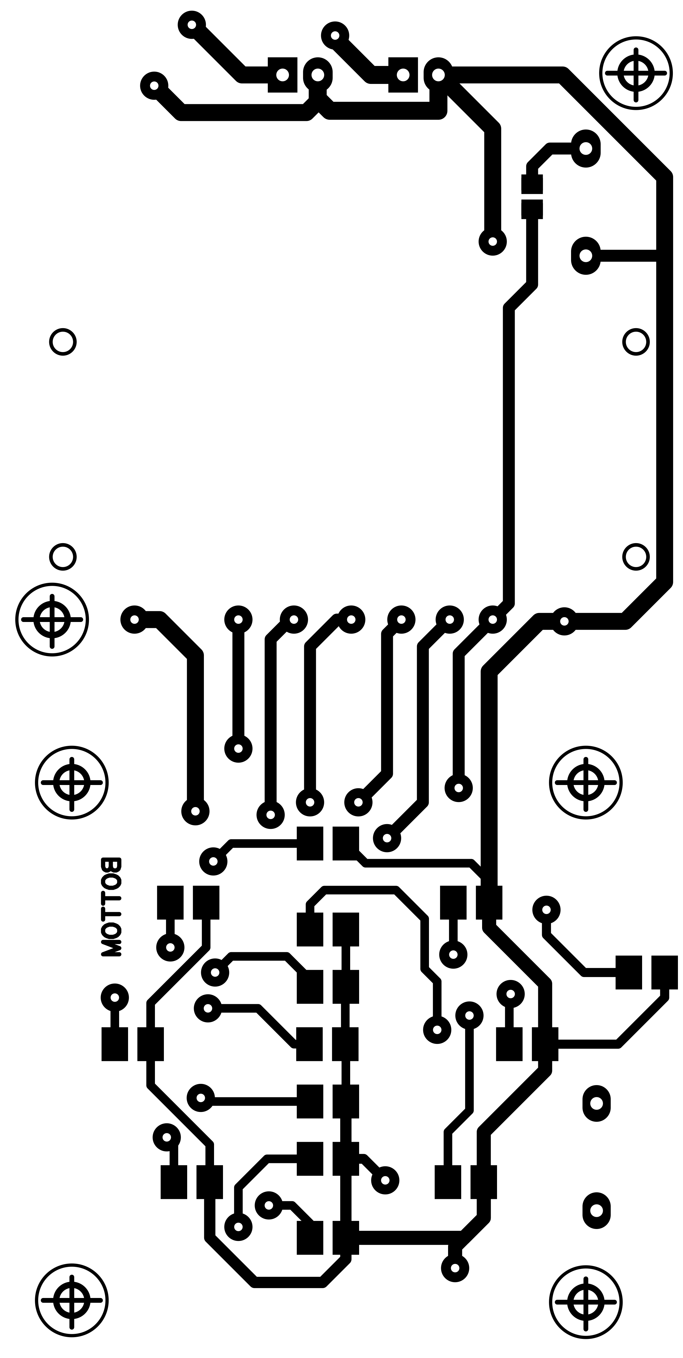
- 101x48mm double face PCB
- around 40 copper 0.8mm rivets (as vias, to solder, to connect PCB layers)
- A few 2mm plastic spacers (6mm, 8mm, 10mm, 12mm), M/M, M/F, screws
- Plastic box components (3D printed, see attachments)
- Simple nylon cord, adhesive male velcro, bi-adhesive tape
- 15cm black wire, 15cm red wire, Heat shrink tube, Kapton isolating tape
The core of the circuit is the MCU Arduino Nano ESP32 that provides to connect the T-Echo by the way of bluetooth-LE, to drive the active buzzer and the NMEA green LED, to instruct the 16 channels 74HC4067 multiplexer to drive the LEDs. I found on the market are present two formats of the 74HC4067 IC, a very small one SSOIP24, and the small one SOIC-24; let buy the small for this circuit and manual soldering. I had an unpleasant experience with bad fuses with 1 ohm resistance instead of nearly 0 (zero) ohm: with this resistance the circuit looses around 0.2V out of 4.0V.
About the LEDs let choose 3mm high efficiency ones producing very good light at low power consumption around 2-6mA as max; I suggest blue colour for the direction, red/orange/green for altitude, green for NMEA receiving.
Despite Nano ESP32 manual suggest to power VIN pin with minimum 6.0V, I tested at 3.4V with good results obtaining the requested 3.3V to power the rest of the circuit using the internal regulator; the power consumption is around 150mA during BLE communication and one LED blinking, this suggest to replace the factory (850mA/h) T-Echo battery with a bigger one as per Li-Ion 3.7V 2100mA/h;
The switch-A on the top is to give power to the circuit, including T-Echo during work and during recharging, the switch-B on the right is to on/off the LED Indicator Circuit only;
The whole circuit can be cutted into two PCBs because is possible to use only the main part with the MCU and the buzzer1 to have only audible warnings without LEDs; in this case you should close (solder) the JP1 jumper near the buzzer1; using whole circuit you will install all components avoiding to install buzzer1 and leaving JP1 open (unsoldered). I did not provide the "cutted" back cover in this case, you should design the 3D printing cover by yourself.
for sure the most difficult task has been the bluetooth-LE connection, I really prefer the old style classic bluetooth, simple, easy, ready to work just after a few minutes of programming. Anyway, the code has been written and works well. The only included library is the ArduinoBLE.h.
At the start the sketch try 10 times to connect the T-Echo that, if it is already switched on, is needed just a few seconds so at 2nd try the connection is done. Then the sketch wait for NMEA sentences with ID "$PFLAU". T-Echo provides even other sentences not needed for this circuit. All accepted sentences are the only with the correct checksum. From "$PFLAU" sentences we have these data (others data fields are not used):
- int nmi_gps // GPS 0=no GPS fix, 1=3D fix on ground, 2=GPS fix when airborn
- int nmi_alarm // ALARM level 0=none, 1=15-20" to impact, 2=10-15" to impact, 3=0-10" to impact
- int nmi_relBearing // RELATIVE BEARING of impact, 0=ahead, 180/-180=behind, -45=left, 45=right, etc.
- int nmi_alarmType // ALARM type 0=none, 2=aircraft, 3=obstacle/zone, 4=traffic advisory, 10-FF other ignored
- int nmi_relVertical // relative VERTICAL distance in meters, positive=OVER, negative=BELOW
- long nml_relHorizontal // relative HORIZONTAL distance in meters
Effectively are used only 3 of them: nmi_alarm, nmi_relBearing and nmi_relVertical. We could have 3 alarm levels: 1=lower=easier, 2=medium, 3=higher=harder. The sketch plays 1 bip and no much fast switching LEDs at 1st level alarm, 2 bips and medium fast at 2nd level, 3 bips and fast switching LEDs at 3th alarm level.
LED status (without active alarms):
- all off = circuit off
- nmea on = T-Echo connected
- nmea 1" blinking = nmea receiving ok
- red 5" blinking = searching T-Echo but not found yet (10 tries)
- red 0.5" blinking = T-Echo not found after 10 tries (to try searching again do a restart switching off/on the power).
On T-Echo settings you have to activate bluetooth NMEA output, then use a computer or a phone to see his broadcasting name that should be something like "SoftRF8605a6-LE" so put the name in the code instead of mine, deviceName[] = "...", save, verify & compile it, transfer the sketch by the way of Arduino on-line Cloud. The Cloud is free for a normal use and limited number of compiling per day. To activate debug code output on Arduino SerialMonitor you have to set this line as "const boolean isDebug=true". To simulate warnings at different levels while you are at home you have to uncomment code lines from 188 to 236, they will override NMEA sentences with simulated alarms so you may listen buzzer and see LEDs working; you could change the pause within alarms changing the line 232 "prevTest=millis()+10000;"; before go flying remember to comment back the part of the code for simulation!
As I already said the bluetooth classic is much simpler to manage but here we have to use Bluetooth-LE, that is totally different and incompatible with the classic one, so forget HC-05, HM-10 or similar modules.
I think my code is simple and linear enough to be readable and understandable in the part regarding bluetooth. Here it is a brief description. Look at the deviceConnect() function: the first thing is to find & connect the T-Echo with BLE.scanForName(deviceName), then connect it with peripheral.connect(); next is to execute peripheral.discoverAttributes() that seems to do nothing but is necessary for the next steps. Now we have to verify the existence of the service with peripheral.hasService(serUUID) and his characteristic with DataService.hasCharacteristic(charUUID) then subscribe to it with DataCharacteristic.subscribe(). Coming back to the main loop(), every time there are datas received we will be informed in DataCharacteristic.valueUpdated() so we have to read with DataCharacteristic.readValue().
The 3D printed enclosure, joining the parts with T-Echo:In download section you may find three files for 3D printing. They have to be connected each other together with your T-Echo.
Preparing your T-Echo for the "marriage": unscrew the two screws on his back, remove the back cover, disconnect the battery; disconnect and unstick the unnecessary flat black NFC antenna placed internally at the bottom; make room for placing the PCB cutting the plastic for around 2.6mm high and 30mm wide at the bottom top edge (see the internal 3D view). Instead of the old screws place a male/female 2mm spacers, 1 x 6mm (bottom left corner) and 1 x 8mm (top right corner) high. Place a piece of bi-adhesive tape externally at the bottom.
Joining the two parts of the LED ring support: put together the two printed parts face to face using 4 x 2mm screws and 4 x 2mm male/female spacers 10mm high;
Preparing the PCB and the LEDs: solder everything on the PCB starting from the around 40 copper rivets (this is not necessary if the PCB has been made from a professional company using instead copper vias to connect the two PCB layers); so proceed with two resistors and two capacitors, then the fuse; at this point is time for the multiplexer, then the Arduino (I suggest to solder just the used pins, and place a piece of Kapton isolating tape at the bottom), the two JST connectors and the buzzer. The final step about soldering components is the LEDs. Try with just one, should be necessary around 10mm of distance between PCB and the holes of the support; the NMEA LED needs more length around 20mm. When all LEDs are in place you may pass to the next step...
Prepare the battery and wires: you have to prepare the two wires, black and red, connecting T-Echo PCB battery connector (1.25mm JST) and the new PCB right connector (2.50mm JST), this wires must pass trough the PCB hole between MCU and JST connectors; check the new Li-Ion battery if the JST connector is the right one (2.50mm JST) and in case change it; CHECK THE POLARITY!
Placing the PCB over T-Echo and LED ring support: if everything is fine you may peel out the protecting paper from the bi-adhesive and stick together T-Echo and ring support aligning them, then put in place the PCB; fasten it with 2 x 2mm nuts in the middle area, with 2 x 2mm female/female spacers 12mm high the bottom area, with 2 x 2mm male/female spacers 12mm high the top T-Echo area (look at the picture below).
The back cover as final step: stick the battery and insert the two switches on the back cover, pass the cord loop, now you may solder the wires between switches and the PCB spots. Finally put all together and screw the last 4 x 2mm screws.
It is time to switch-on the top switch and see T-Echo starting, then switch-on the right switch to see LED ring doing the initial show and try to connect via Bluetooth the T-Echo. After a few seconds, ones the BLE connection is done, you will see the NMEA green LED blinking: it works!
Your T-Echo extension is ready to go airborne: happy landings!
PCBWay Services:Even this time I decided to try the famous and popular PCBWay services. Some our beautiful project deserve a real professional service giving to them precise and superb items like PCB and 3D enclosure/component. I visited for the first time PCBWay website last year (http://www.pcbway.com) and after a few minutes I had been able to obtain the final price of the PCB just uploading the.ZIP Gerber file and setting some preferences of the board like colour: I choosen the blue but is still available the most popular green, or a shining white, red or others. They shown to me a preview of the board: impressive.
The same for the 3D printings (just uploading the.STEP or .STLfile/s) and you cannot image how many materials are available: PLA, ABS, PETG, Resin, Polycarbonate but as well as Aluminium or Steel or... Titanium! What, Titanium?! It is incredible.
They offer other services actually I have not tried them yet but with these two I can say I am very satisfied. Shipping time were quick. The price was adequate. The customer care office and technician production office demonstrated to me to be ready and "sharp" for details.
News / Updates:- 12.05.2025 - 3D printing models: I just published even on GrabCAD website the 3D parts you may print for this project.
- 13.05.2025 - If you wish I have a few PCB from PCBWay ready to solder the components on, I can send to you one if still available: first come first served.
- 19.06.2025 - I suggest to modify the code, the first lines of goLeds() function as follows for a more precise and sensitive altitude separation shown on LEDs:
if (nmi_relVertical >= 150){  // set altitude leds
    schemaAlt=15;
}
if ((nmi_relVertical > 50) && (nmi_relVertical < 150)){
    schemaAlt=14;
}
if ((nmi_relVertical >= -50) && (nmi_relVertical <= 50)){
    schemaAlt=13;
}
if ((nmi_relVertical < -50) && (nmi_relVertical > -150)){
    schemaAlt=12;
}
if (nmi_relVertical <= -150){
    schemaAlt=11;
}
Enjoy the project making and using it! :-)


Comments