


Hardware components | ||||||
| × | 1 | ||||
| × | 1 | ||||
| × | 1 | ||||
| × | 1 | ||||
 |
| × | 1 | |||
 |
| × | 1 | |||
| × | 1 | ||||
 |
| × | 1 | |||
| × | 2 | ||||
 |
| × | 1 | |||
 |
| × | 2 | |||
 |
| × | 2 | |||
 |
| × | 2 | |||
| × | 1 | ||||
 |
| × | 1 | |||
Hand tools and fabrication machines | ||||||
 |
| |||||
This is version 2 of my original audio amplifier project. The old one was very much a prototype, and quite honestly, it was really just a mess of wires. A lot has been updated about the original version, but the main addition is a microcontroller to control I/O selection and a display to show some information from the amplifier.
FeaturesAmplifier:
The 3e-Audio TPA3255 amplifier module is configured in a 2x260W (1% THD+N) @ 4Ohm mode. It uses a class D amplifier chip from Texas Instruments that is rated for ~111dB dynamic range, < 0.01% THD+N for 0.3W-200W, 80dB PSRR, ~90% efficiency
Preamp:
The preamp and MCU board is a custom PCB that I designed awhile back. If the 3.5mm input is selected, the preamp takes the single-ended input signal from the 3.5mm jack and converts it to a differential signal. Input selection is based on some small-signal mechanical relays on the PCB. The differential signal from the converted 3.5mm input or the differential signal from the XLR inputs is then amplified based on the value of the volume control potentiometers on the front of the chassis and sent to the amplifier module in order to drive the speakers. The audio signal read by the MCU is taken from between the conversion to differential and the potentiometers. This means the amplitude of the signal read by the MCU is entirely dependent on the amplitude of the input signal and does not vary based on the resistance value on the potentiometer. This decision was a personal preference and could easily be changed so that the signal is read between the potentiometers and the amplifier module.
I will not be posting the design for this PCB publicly because it's not a particularly great design. It was my first PCB design, and I have modified the board a bit since getting it printed. If you really want to know about the design of the preamp/MCU board, direct message me, and we can talk about it.
I/O:
There are two sets of inputs and outputs. For inputs, either a stereo 3.5mm aux cord or a pair of XLR connectors can be used. The outputs consist of a pair of SpeakOn connectors and a pair of speaker binding posts. Using the display, the user can switch between the various inputs and the outputs. The switching mechanism utilizes mechanical relays as opposed to solid-state relays/switches for better audio performance.
Display:
The touchscreen display is used to control I/O selection and fan speed, reset the amplifier, display fault and clip states, show a vu-meter, and display a realtime analyzer using FFT. Each menu page is explained in the "Menu" section of this project write-up.
Programming/MCU:
This project uses a Teensy 4.0 as the interface between the display and the rest of the amplifier. Since the FFT and vu-meters are meant to mainly be fun, visual effects, audio from both channels is read in using the Teensy's built in ADC. The code for the Teensy utilizes DMA to read values from the ADC, and all major math operations are performed using CMSIS DSP library functions.
The vu-meters use either an A or C weighting filter in order to show RMS levels nearer to how humans perceive relative loudness at different frequencies. Either the A or C filter coefficients can be chosen at compile time.
The built-in EEPROM on the Teensy is used to store the configured fan speed, the selected input, and the selected output. This allows the amplifier to remember and restore settings even after being powered off.
ExternalsChassis:
I bought this chassis off of eBay and used a Dremel and a drill press to cut out the holes on the front and rear panels as well as the mounting holes for the electronics modules on the bottom plate.
Front Panel:
The front panel includes a power switch, two potentiometers (one for each channel), and the display.
Rear Panel:
The rear panel houses the inputs, outputs, and AC power connection. Inputs include a 3.5mm stereo jack and two balanced XLR inputs. Outputs consist of a pair of 4-pole SpeakOn connectors and a pair of speaker binding posts. A C13/14 power socket with an 8A fuse is used to connect the power supplies to wall power.
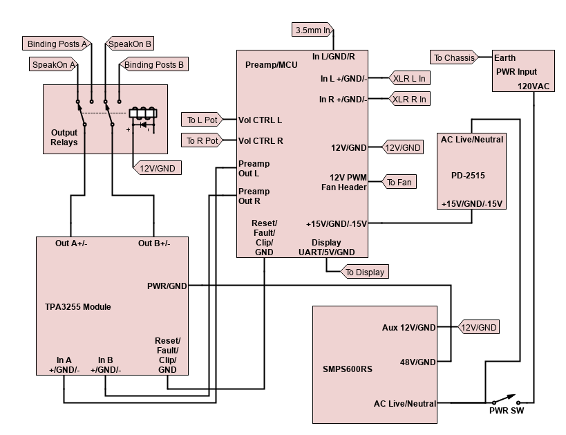
InternalsA schematic can be viewed below in the "Schematics" section. The various boards are labeled in the second picture. The fan is attached to the top panel above the amplifier module and is not shown in any pictures.
Menu/DisplayMain Menu:
The main menu has buttons to access the submenus along with a button to initiate the reset mode in the amplifier module. There are also indicators to show when the amplifier senses it is clipping or in a fault state. On the far right, the two bars are a weighted vu-meter for the left and right channels. Amplitude for the vu-meters are measured in dB.
Input Menu:
The input menu allows the user to select between the 3.5mm aux input and the XLR inputs. Changing the inputs results in the amplifier being put into a reset state and the input selection relays switching. This prevents popping when the relays switch between different inputs. The green box indicates which input is currently selected.
Output Menu:
The output menu allows the user to select between the speaker binding posts and the SpeakOn outputs. Changing the outputs results in the amplifier being put into a reset state and the output selection relays switching. This prevents popping when the relays switch between different outputs. The green box indicates which output is currently selected.
FFT Menu:
The FFT page shows the frequency composition of the input signal in (roughly) 1/2 octave bands. The checkboxes on the top right of the page enable and disable channels. When both channels are enabled, a purple section of the band indicates the amplitude of the signal in that frequency band for both channels. When one of the channels has a higher amplitude signal for a frequency band, the band color above the purple part of the band will indicate the signal amplitude of that channel in that frequency band. I.E. whenever the left channel has a higher amplitude than the right channel for a specific frequency band, the purple section of the band will indicate the signal amplitude of the right band at that frequency and the blue box above the purple will indicate the amplitude of the left channel.
When only one channel is selected, the signal amplitude for each band is displayed by one color. The left channel is shown in blue, and the right channel is shown in Red.
It is pretty straightforward to change these colors in code if you use any of the FFT display code for your projects. Change FFT_COMBINED_COLOR in AmpDisplay.h. The color codes are in RGB565 format.
Fan Menu:
The fan page is used to control the speed of the 12V fan. The slider is used to change the PWM duty cycle, which changes the fan speed. The gauge shows the current fan speed percent.
Amplifier PerformanceUnfortunately, I don't own the equipment to get decent quantitative results, but this amplifier is, by far, one of the best that I have ever heard. It has exceptional dynamic range, an inaudible noise floor, and can drive moderately large speakers very well. It may not be powerful enough to really drive large speakers at higher volumes, but for the speakers I have, it is perfect.
At max volume, there is a small bit of high frequency hiss, but it's really only audible within about a foot of the speakers in a quiet listening environment.
All of the control functions seem to be working reasonably well. My only complaint is that display doesn't do a great job of handling the FFT page. It's being sent a lot of commands at once for each frame, and it handles it well enough to be useable. However, it occasionally skips drawing a couple of the frequency bands.


Comments