Hello everyone! For my EDES 301 project, I decided to build a smart checkers mechanism that can move pieces automatically using a CNC-style structure. The goal was to attach a strong neodymium magnet to the Z-axis so it could grab magnetic pieces from underneath the board, move them to a new location, and release them by lowering the Z-axis.
I also used a webcam to detect the board and pieces. The plan was to input the current and destination coordinates of a piece, and then have the system find the best path that avoids other pieces while moving it. The mechanism works like this: after I enter a square, it moves in X and Y directions to that spot, raises the Z-axis to attach the piece magnetically, moves to the destination with the piece held up, and finally lowers the Z-axis to release it.
The ProcessMechanical AssemblyI began by ordering all necessary components and building the CNC-style frame. I used Nikodem Bartnik’s Dremel CNC design to 3D print parts with the recommended settings. First, I assembled the base using aluminum extrusions and M5 screws. I inserted bearings into the 3D-printed holders for the X, Y, and Z axes, then slid in the linear rods through the linear bearings. I attached the lead screws using couplers to connect them to the stepper motors.
Next, I laser-cut (engraved) a wooden board and mounted it above the CNC structure using a 3D-printed holder. For the Z-axis, I 3D printed a magnet holder and attached it to the moving Z component. To handle homing, I installed six limit switches (min and max for each axis) and positioned them carefully. I also designed and printed L-shaped mounts to hold the Y-axis switches.
Electrical AssemblyTo control the motors, I used a CNC shield. This made it easy to organize all the stepper motor connections in one place. I placed step jumpers on the board to slow down the motors, which gave me more precise control and helped avoid putting too much torque on them.
One important problem I had to solve was the voltage difference between the CNC shield and the PocketBeagle. The CNC shield runs at 5V logic, but the PocketBeagle can only handle 3.3V on its GPIO pins. To fix this, I used level shifters to safely convert the signals between the two. I connected the low-voltage side (LV1, LV2, LV3, LV4) of the level shifters to the STEP and DIR pins for each axis on the CNC shield. Then I connected the high-voltage side (HV1, HV2, HV3, HV4) to the GPIO pins on the PocketBeagle.
For power, I used a 24V power supply and added a voltage regulator in case I needed to adjust the voltage going into the CNC shield. I connected the + and – terminals of one side of the voltage regulator to the power supply and the other side to the CNC shield's power input. Then, I took the 5V output of the CNC shield and connected it to the HV pin of the level shifter. I also connected the LV pin of the shifter to the PocketBeagle so the signal could be translated safely between the devices.
I made sure everything had a shared ground by connecting the ground pins from the PocketBeagle, CNC shield, and level shifter all together on a breadboard.
Once the power and control signals were set up, I inserted the motor drivers into the CNC shield and connected the stepper motors for the X, Y, and Z axes.
For homing, I used 6 limit switches—two for each axis (min and max). I connected each switch’s NO (normally open) pin to a GPIO pin on the PocketBeagle using jumper wires. Then I connected each switch’s C (common) pin to the shared ground. To hold the limit switches securely in place, I 3D printed brackets, including L-shaped mounts for the Y-axis switches.
This setup gave me full control over motor direction, speed, and position through the PocketBeagle and CNC shield, with safety features from the limit switches built in.
Z and X Axis Min Limit Switches
I wrote motor control and homing scripts on Cloud9 (which runs on the PocketBeagle). However, since the webcam connects via USB to the computer, not the Beagle, I couldn’t access the camera directly from the Beagle. To fix this, I wrote a server script on the PocketBeagle and connected it to a controller script on VS Code. I also wrote a remote motor control script in VS Code that sends commands to the Beagle over a socket connection.
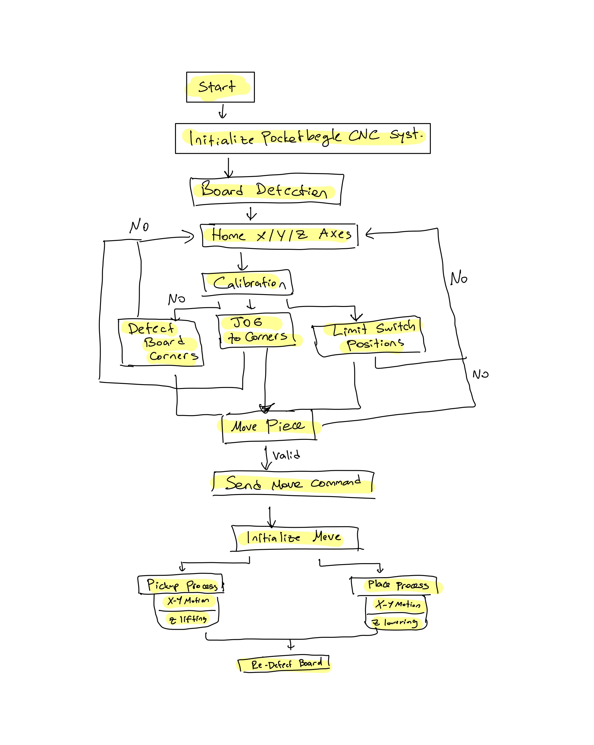
The homing script detects the max and min limit switch positions for each axis and then sends the mechanism to the center of the range. Since the CNC and the board use different coordinate systems, I had to calibrate them. I tried three methods:
1)Vision-Based Calibration: I used the camera to detect board corners and input the board size to calculate square sizes. But the results weren’t accurate enough.2) Manual Jog Calibration: I moved the CNC head to each corner using the keyboard and recorded the coordinates. This worked but was slow because it required lots of key presses.3) Limit-Based Calibration: This was the final method I used. I measured the distance between the min and max limit switches, then divided that by 8 (since the board is 8x8 squares) to get the size of each square. When I input a square like (x=1, y=5), it calculates how far that is from the axis’s min limit position
Even though the math was correct (I confirmed this with debug prints), the CNC still doesn't move to the right Y location due to a bug I haven’t found yet. All calibration functions were split into separate scripts for clarity.
Future PlansFix the Y-axis calibration bug so the movement is accurate.
Add piece detection using the camera and plan motion paths that avoid other pieces on the board.
Videos
Homing:
Piece Movement:


_6gzZbapoMP.jpg)


_3u05Tpwasz.png?auto=compress%2Cformat&w=40&h=40&fit=fillmax&bg=fff&dpr=2)
_6gzZbapoMP.jpg)
Comments