


See also the minifarm control system built with MM6D, MM7D, MM8D and MM9A equipment!
1. Technical data- Supply voltage: 230V AC
- Auxiliary voltage: 24V DC
- Supply current: max. 8.5 A (with load)
- Mechanical size: 230x190x90 mm
- IP protection: IP 56
- Mass of cover: termoplast (ABS)
Maximal load of outputs:
- Electromagnetic valveoutputs: 24V DC 0.5A
- Water pump output: 230V AC 8A
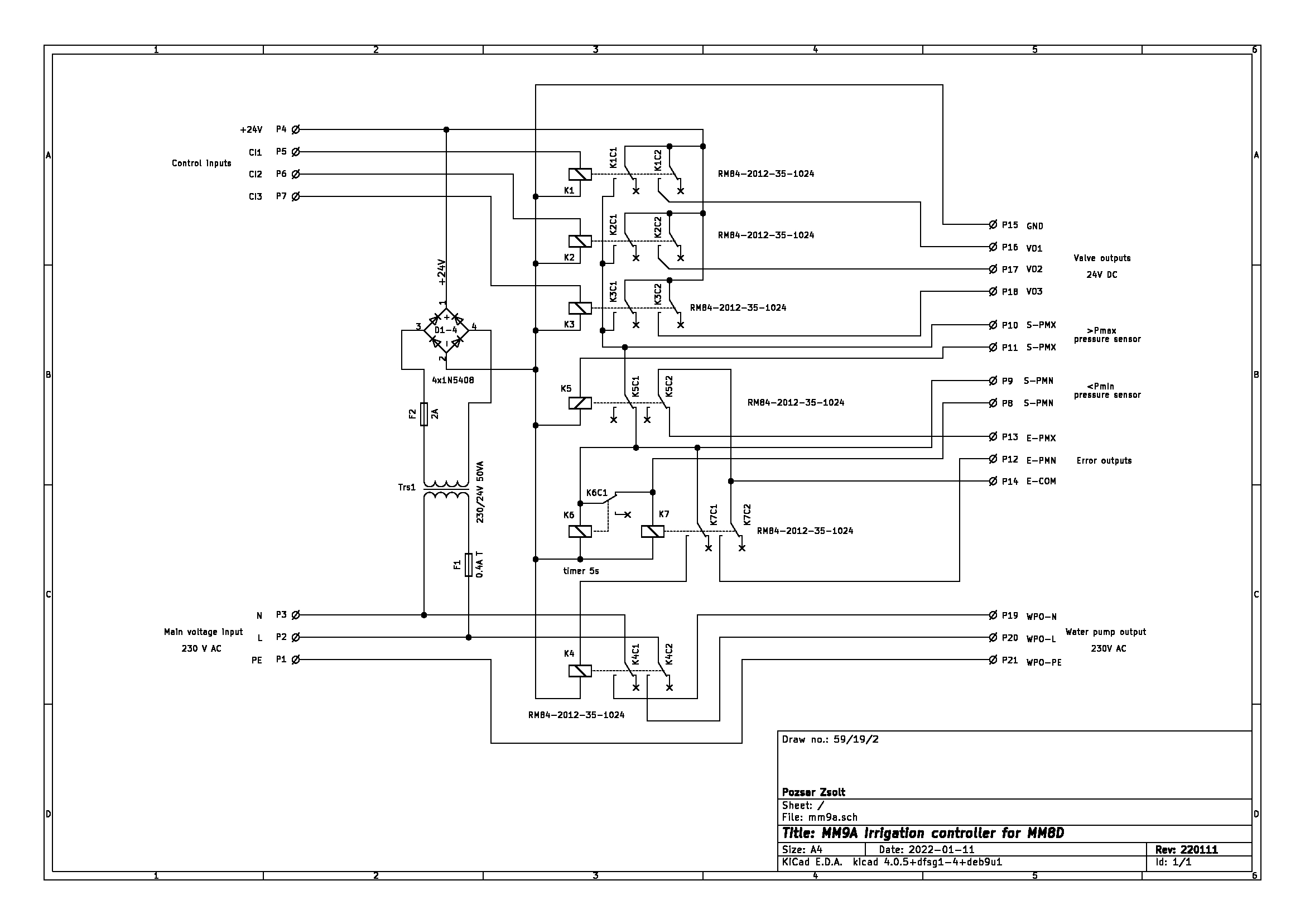
The device is used to switch the valves and pumps of the irrigation system on and off in cooperation with the MM8D.
The device has three control inputs, three 24V DC valve outputs, one 230V AC pump output and two pressure fault relay contact outputs. To activate the inputs, the auxiliary voltage must be connected to them. When any input is activated, the pump output also turns on. If the water pressure exceeds the set value (eg. clogging), the pump output is switched off and the >Pmax output is switched on. If the water pressure falls below the set value during operation (eg. lack of water), the pump output is switched off and the the <Pmin output is switched on.
This device is a part of my growing site control system.
3. Internal structure- 1: Fuse (F1)
- 2: Transformer (Tr1)
- 3: Fuse (F2)
- 4: Graetz bridge (D1-4)
- 5: Relays of valve outputs (K1-3)
- 6: Relay of water pump output (K4)
- 7: Relay of >Pmax error output (K5)
- 8: Relays of <Pmin error output (K6-7)
- 9: Connectors (P1-21 - from top to bottom)
- 10: Mounting holes
You can download schematic as part of the complete documentation or in separate PDF, SVG and KiCAD formats from the developer/manufacturer's website.
5. Terms of useHardware documentation can be modified and/or redistributed under the Creativ Commons 4.0 Attribution Non-Commercial (CC-BY-NC-4.0) License.
6. Downloadable documentationThe complete documentation of the hardware in the.tar.gz format compressed file can be downloaded from the homepage or Github.

Comments