

Hardware components | ||||||
 |
| × | 1 | |||
 |
| × | 1 | |||
| × | 1 | ||||
Software apps and online services | ||||||
 |
| |||||
| ||||||
| ||||||
| ||||||
 |
| |||||
Cattle farming is very important because it provides meat, milk and other dairy items, as well as calfskin and other derivatives. These products and bi-products play a vital role in human life. Besides, cattle are farmed in areas where harvests can’t be effectively developed and dairy cattle give work and food security to many people. Moreover, cattle excrement is commonly used as soil fertilizer.
On the other side, cattle diseases are a very common problem in farms and challenge food production efficiency and sustainability. For that reason, it is crucial for a farmer to have a well managed and disease-free herd, so it can lend optimum production.
Common cattle diseases, such as Bovine Respiratory Disease, Mastitis in Cows, Calf Scour, Pink Eye, Bovine Viral Diarrhea, Mad Cow Disease, etc. are infectious diseases caused by bacteria. They are diagnosed via microscopic examination of blood, feces and tissue samples. Appropriate treatment involves the prescription of antibiotics, antiparasitics, antiseptics and other chemical substances. Farmers especially in underdeveloped countries normally don't have easy access to diagnosis and treatment for their cattle. Less if they live in remote areas, where there aren't veterinary doctors nor analysis laboratories.
Drones are a revolutionary technology with the potential of impacting a wide range of applications. One of those applications is autonomous drone delivery, which can positively impact sustainable food production, especially regarding cattle farming. Drones can transport biological samples for diagnosis from remote areas to diagnostics laboratories. After the diagnostics, they can transport back prescribed medicine for the cattle.
However, in order to enable safe autonomous drone delivery, a drone must be equipped with an obstacle detection and avoidance system. Such system will make possible for the aircraft to safely fly long distances, without the need of a dedicated pilot or an operator monitoring the drone to avoid crashing against obstacles in its path.
In this project I build an AI computer vision based obstacle detection and avoidance system for drones. The system supports the MAVLink protocol to seamlessly integrate with any PX4-enabled multirotor or fixed wing drone. It provides obstacle detection and avoidance for long-distance, safe autonomous flight.
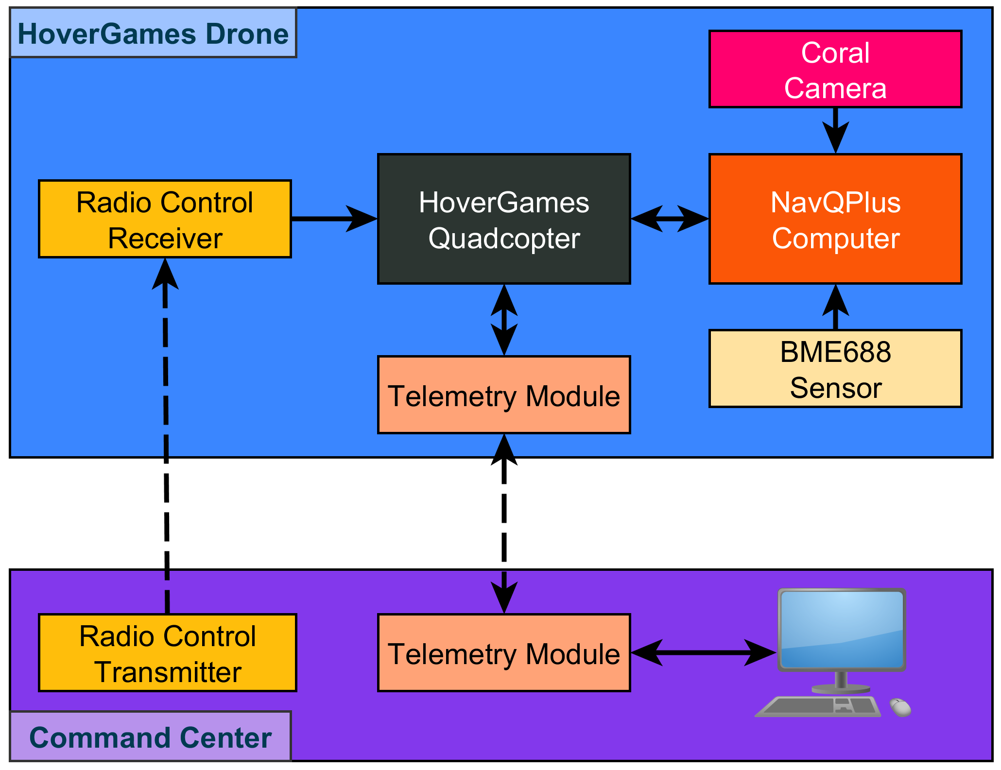
System Block DiagramFigure 1 shows the main hardware components for the drone and command center. The NavQPlus onboard computer and the Coral Camera are used for computer vision to detect airborne objects, such as airplanes and parachutes. All other devices are commonly used to operate a PX4-based drone.
Figure 2 shows the drone assembled and ready to fly. The drone was tested to fly operated by the RC transmitter but not controlled by the NavQPlus computer.
The Coral camera was mounted on a camera gimbal for automatic image stabilization to ensure a "fixed" Cartesian coordinate in the camera field of view with respect to the horizon. This makes much more easy the avoidance velocity vector computation.
The software was developed using SITL simulation on an Ubuntu 20.04 PC with ROS 2 Foxy and was tested in the last development steps on the NavQPlus. Because the NavQPlus runs the same operating system, the software running in both platforms are 99% identical.
Functional Descriptiona) Planning RoutesTo send biological samples from the farm to a remote diagnostics facility, a waypoint mission must be carefully prepared. Figure 3 shows an example of an autonomous mission. As it can be seen in 2D graph located at the lower section, planned waypoint altitudes follow the natural irregularity of the terrain. Moreover, waypoints are located to avoid flying the drone over populated areas. To validate the planned route safety, the mission can be tested with a real-time video transmission and control with a LTE control and telemetry system. This, to ensure visually the route follows the terrain properly and avoids the natural obstacles.
After the drone is loaded with the corresponding mission plan, the Mission is automatically executed by the software running on the NavQPlus computer. The drone will automatically take off and start navigating the mission waypoints. The obstacle detection and avoidance system is running as well on the NavQPlus onboard computer. Anytime a flying object is detected in the drone camera's field of view, the computer will take control of the drone after sending a ROS message to the drone's flight controller to change from Mission to Offboard mode. In Offboard mode, the NavQPlus onboard computer directly controls the drone's velocity in the local XYZ coordinate system and will compute the appropriate velocity components (Vx, Vy, Vz) to control the drone in order to perform the required avoidance maneuver.
Figure 4 shows how the onboard computer computes the avoidance vector. The purple line represents the detected aircraft's position vector in the camera field of view Cartesian coordinate system. The green line represents the computed avoidance vector. The avoidance vector direction is the opposite to the aircraft's position vector and its module is proportionally inverse to the aircraft's position vector module. For instance, if the purple line is small, that is the aircraft position is near the field of view center; the green line is proportionally large, that is the avoidance velocity's module must be higher to avoid the aircraft because it is right in front of the drone.
c) Computer Vision SystemThe computer vision system for object detection is based on a 'ssd-mobilenet-v2-fpnlite-320' deep learning model retrained using transfer learning to detect the airborne objects. For the present prototype I trained it to detect just airplanes and parachutes for simplicity, because the training process is very time consuming. Sadly, I couldn't use NXP's eIQ deep learning platform because the resulting models had a confusing data output structure and no practical help was found on the official forums to interpret and use this models properly.
For that reason, I had to use Google Colab to train the model. Each training sessions lasted about 4.5 hours using 40000 steps with a dataset of about 400 training images in total for both classes (airplane, parachute). The obtained detection confidence was between 30% and 60%, which can be improved with a larger dataset and better image selection.
I prepared a dataset by combining images downloaded from the Internet and Amazon Prime Air's Airborne Object Tracking (AOT) dataset. Because I didn't have available an appropriate training machine at hand, I used just a very small fraction of the AOT dataset.
Figure 5 shows an example of the images from my training dataset. The black and white images are from the AOT dataset.
ROS 2 and PX4The software running on the NavQPlus onboard computer is based on Robot Operating System version 2. The NavQPlus board runs Ubuntu 20.04 and ROS 2 Galactic was installed as well, along with PX4 software. The system has basically two ROS 2 nodes:
a) Computer vision node: Written in python, it implements the object detection inference with Tensorflow Lite and the calculation of the avoidance vector. It also publishes a ROS topic with the coordinates of the computed avoidance vector.
b) Offboard navigation node: Written in C++, it implements the drone navigation control. It subscribes to the avoidance vector topic published by the computer vision node and computes the avoidance velocities (Vx, Vy, Vz) to perform and avoidance maneuver when an airborne object is detected. When this node is executed, it arms the drone to take off and changes flight mode to Mission to execute a previously uploaded plan. When an obstacle is detected during the mission execution, it automatically changes to Offboard flight mode to perform the avoidance maneuver. Once the obstacle is out of the camera field of view, it commands the drone to resume the mission.
Some Software DetailsThe flight mode change is handled in the ROS 2 offboard node with a Finite State Machine:
switch(vehicle_state) {
    case STATE_TAKING_OFF:
        // Arm the vehicle
        this->arm();
        this->publish_vehicle_command2(VehicleCommand::VEHICLE_CMD_DO_SET_MODE, 1, 4, 4); // Mission
        ////// this->publish_vehicle_command2(VehicleCommand::VEHICLE_CMD_DO_SET_MODE, 1, 4, 2); // Takeoff
        vehicle_state = STATE_FLYING_MISSION;
    break;
    case STATE_FLYING_MISSION:
        if(vehicle_local_pos.z <= -MIN_AVOID_ALTITUDE && avoid_coord_flag) {
            vehicle_state = STATE_AVOIDING;
            is_avoiding = true;
        }

    break;
    case STATE_AVOIDING:
        // Drone < Camera
        // X < X | Z < Y
        x_vel = (avoid_coord.x/y_ax_pos) * MAX_X_VEL;
        y_vel = (avoid_coord.y/x_ax_pos) * MAX_Y_VEL;

        // Compute avoidance velocities in NED coord.
        desired_vel_e = x_vel*cos(yaw);
        desired_vel_n = -x_vel*sin(yaw);

        if(vehicle_local_pos.z < (-MIN_AVOID_ALTITUDE)) { // Command lower altitud if min. not reached
            desired_vel_d = -y_vel;
        } else { // Do not go below min. altitude
            desired_vel_d = 0.0;
        }

        offb_ctrl_mode_msg.velocity = true;
        traj_setpoint_msg.velocity = {desired_vel_n, desired_vel_e, desired_vel_d};

        // Set last known yaw angle from Mission mode
        offb_ctrl_mode_msg.attitude = true;
        traj_setpoint_msg.yaw = yaw; // [-PI:PI]


        if (offboard_setpoint_counter_ == 10) {
            // Change to Offboard mode after 10 setpoints
            this->publish_vehicle_command(VehicleCommand::VEHICLE_CMD_DO_SET_MODE, 1, 6); // Offboard
        }

        //offboard_control_mode needs to be paired with trajectory_setpoint
        publish_offboard_control_mode();
        publish_trajectory_setpoint();

        // stop the counter after reaching 11
        if (offboard_setpoint_counter_ < 11) {
            offboard_setpoint_counter_++;
        }

        if(!avoid_coord_flag) {
            vehicle_state = STATE_FLYING_MISSION;
            is_avoiding = false;
            this->publish_vehicle_command2(VehicleCommand::VEHICLE_CMD_DO_SET_MODE, 1, 4, 4); // Mission
            offboard_setpoint_counter_ = 0;
        }

    break;
    case STATE_LANDING:
    break;
    default: break;
}
Avoidance velocity computation code snippet:
// Drone < Camera
// X < X | Z < Y
x_vel = (avoid_coord.x/y_ax_pos) * MAX_X_VEL;
y_vel = (avoid_coord.y/x_ax_pos) * MAX_Y_VEL;

// Compute avoidance velocities in NED coord.
desired_vel_e = x_vel*cos(yaw);
desired_vel_n = -x_vel*sin(yaw);
Please see the submitted code files for complete code listings.
Conclusion
This project is a work in progress. There's much to be done in terms of developing particularly the software but also the hardware. The present documentation needs also to be completed. Sadly, I didn't have the necessary time to complete all project goals.
Comments