


Hardware components | ||||||
 |
| × | 1 | |||
 |
| × | 1 | |||
Software apps and online services | ||||||
 |
| |||||
| ||||||
 |
| |||||
| ||||||
Hand tools and fabrication machines | ||||||
 |
| |||||
 |
| |||||
 |
| |||||
What if the best way to learn electronics was to debug a real-world problem?
That’s the idea behind Bug in Circuit, an IoT relay board designed for STEM learning and maker education. The board comes fully assembled—with one small catch: a bug in the relay circuit! Your challenge? Find it. Fix it. Make it work.
This kit is more than just another IoT switch. It's a fun, hands-on lesson in problem-solving, circuit analysis, and embedded development, all packed into a beginner-friendly format using the ESP32.
ESP32-based board with 2/4/6-channel relay variants
- ESP32-based board with 2/4/6-channel relay variants
One intentionally placed bug in relay logic to troubleshoot
- One intentionally placed bug in relay logic to troubleshoot
Header pins for sensors and input devices
- Header pins for sensors and input devices
IR and RF control interface
- IR and RF control interface
Alexa/Google Assistant integration
- Alexa/Google Assistant integration
Real-time cloud dashboard support
- Real-time cloud dashboard support
Built-in 230V to 5V converter (6-channel variant)
- Built-in 230V to 5V converter (6-channel variant)
Debugging is one of the most important skills for engineers and makers, but rarely is it taught as a standalone experience. With Bug in Circuit, students learn:
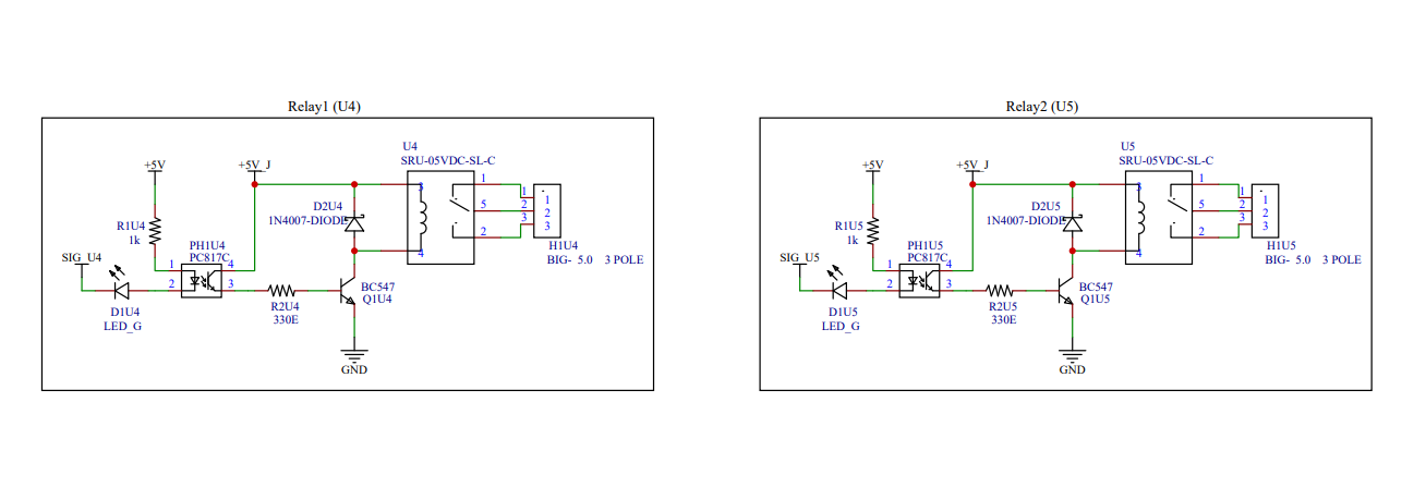
How to read schematics and trace connections
- How to read schematics and trace connections
How to use a multimeter and logic probe
- How to use a multimeter and logic probe
How to write and upload firmware to ESP32
- How to write and upload firmware to ESP32
How to test and verify a circuit works
- How to test and verify a circuit works
How to interface sensors and use IoT platforms
- How to interface sensors and use IoT platforms
This board has been featured in Electronics For You Magazine and is already being used in workshops at SRM University and IIT Research Park.
You can find the schematics and board layout on GitHub (or insert your link here).PCB design is done in KiCad and optimized for DIY assembly.
Codecpp
CopyEdit
// Sample sketch to control relay 1 via cloud
int relayPin = 13;

void setup() {
  pinMode(relayPin, OUTPUT);
  digitalWrite(relayPin, LOW); // Off by default
}

void loop() {
  // Replace with your IoT or logic control
  digitalWrite(relayPin, HIGH);
  delay(1000);
  digitalWrite(relayPin, LOW);
  delay(1000);
}
cpp

CopyEdit
// Sample sketch to control relay 1 via cloud
int relayPin = 13;

void setup() {
  pinMode(relayPin, OUTPUT);
  digitalWrite(relayPin, LOW); // Off by default
}

void loop() {
  // Replace with your IoT or logic control
  digitalWrite(relayPin, HIGH);
  delay(1000);
  digitalWrite(relayPin, LOW);
  delay(1000);
}
Power up the board via USB or 5V DC input
- Power up the board via USB or 5V DC input
Open Arduino IDE and upload your code
- Open Arduino IDE and upload your code
Use a multimeter to trace the relay not working
- Use a multimeter to trace the relay not working
Find the bug: is it wiring? logic level? transistor?
- Find the bug: is it wiring? logic level? transistor?
Fix it—using soldering, code or component swap
- Fix it—using soldering, code or component swap
Celebrate your working smart switch with Alexa/Google voice!
- Celebrate your working smart switch with Alexa/Google voice!


Comments