

Hardware components | ||||||
 |
| × | 1 | |||
| × | 2 | ||||
| × | 2 | ||||
| × | 1 | ||||
| × | 1 | ||||
| × | 1 | ||||
 |
| × | 1 | |||
| × | 1 | ||||
| × | 1 | ||||
Software apps and online services | ||||||
 |
| |||||
This project was made for a home automation project for a physical computing class. The goal of the home automation project was to find something in your house to automate using electronics. I chose to automate my curtains since I often forget to open and close them. My project solves this issue by automatically opening and closing the curtains based on the light level outside and how bright you want it to be.
Parts of the Project- Motor Circuit
- Light Sensing Circuit
- Position Circuit
- Mechanical Structure
- Full Assembly
The first part of the project is getting the motor circuit to work since without a functioning motor circuit, the core aspect of the automation wouldn't work. The motor used was a 36W 40W 12-24DC permanent magnet motor. This motor was chosen since moving the physical curtains would take a large amount of force.
To power the motor, a 12V DC power supply was used in conjunction with a PWM speed controller.
To control the direction the motor spun and when the motor would spin, two optocoupler relay modules were used. The relay modules (see Relay Module Schematic below for more detailed information on the relay module circuit) were used to electrically isolate the microcontroller from the 12V power supply that powers the motor. Connected to each end of the relay module is either the live or ground from the speed controller which is connected to the 12V power supply. The other side of the relay modules are each hooked up to a digital pin on the microcontroller so that the relays can be individually switched on and off to allow for current to flow through the motor to spin it. Switching on one relay to high and keeping the other low will spin the motor one direction and reversing which relays are switched on spins the motor a different direction.
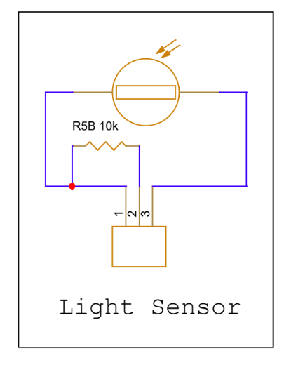
Light Sensing CircuitTo detect brightness level an LDR Module (see LDR Module Schematic below for more detailed information about the LDR Module circuit) was used. The LDR module gives an analog signal by using a photoresistor, a variable resistor dependent on light, to vary a voltage that corresponds to a light level. This value is what the brightness is outside and can be read by the microcontroller through an analog pin.
To set the brightness level you want a potentiometer is hooked up to microcontroller, which can be used to receive an analog value. With these two values, you can use software to compare the two values to know if it is brighter or darker than what you want it to be (both analog value should be on the same number range).
The actual lumen value of the outside brightness is not needed to be known since we are just trying to see if it is brighter or darker than what you set the brightness level to.
Position CircuitThe position circuit tells the microcontroller weather the curtains are currently closed open. One limit switch will be on the left side and the other will be on the right side. Pushing one limit switch will allow the microcontroller to know whether or not the curtains are open.
The two limit switches were set up with common hooked up to ground and normally closed connected to a digital pin set to input pull up.
Mechanical StructureThe mechanical structure was the most difficult part of the project. The mechanical structure was designed around a pulley system that moved a hanging mass that could hit the limit switches. This is where most things went wrong.
The logic behind the automation is to first check the position of the curtains, whether it's open or not, then check if it is brighter than what you want it to be. The curtains would then open or close based on the two logic statements. For example, if the curtains are closed and it is brighter than your set value, the curtains will open until it hits the opposite limit switch at which point the motor will stop spinning.
The issue with this was that physically the hanging mass would not continue to press the limit switch after the motor stopped spinning. The solution to this was to continue to push the hanging mass into the limit switch after the full movement from one side to the other. This is very bad for the motor, so this should be treated as a temporary solution to prevent the motor from overheating.
Another issue was the instability of the mechanical structure. The only solution to this would be to more permanently secure the structure which was not possible for this project.
Fully Assembly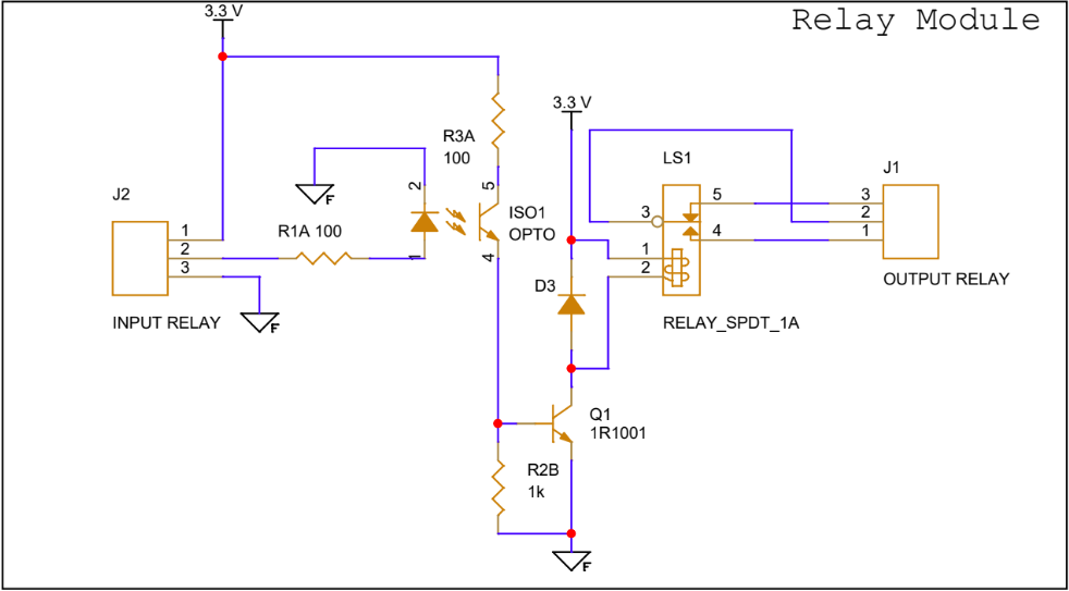


Comments