


Hardware components | ||||||
_ztBMuBhMHo.jpg?auto=compress%2Cformat&w=48&h=48&fit=fill&bg=ffffff) |
| × | 1 | |||
 |
| × | 1 | |||
 |
| × | 1 | |||
| × | 1 | ||||
| × | 1 | ||||
Software apps and online services | ||||||
| ||||||
 |
| |||||
| ||||||
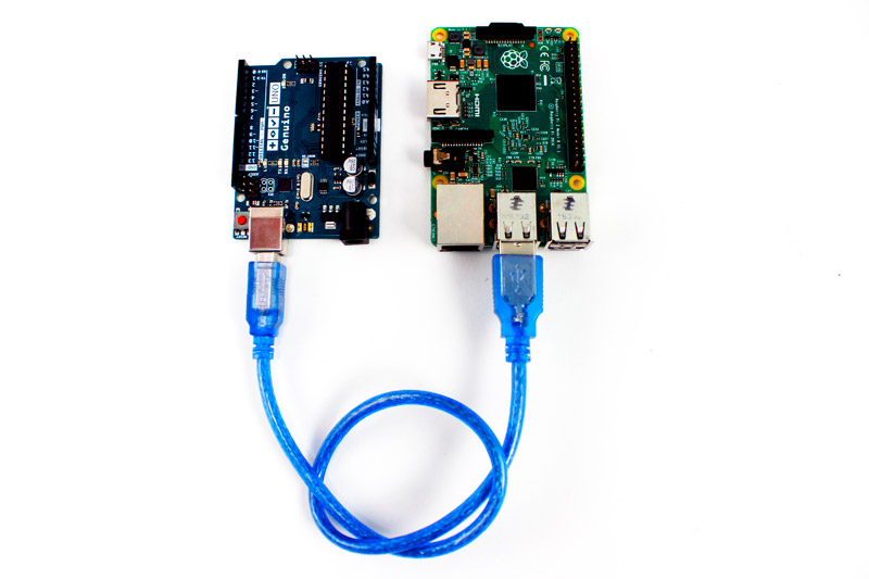
Well a 4-wheeled command controlled navigating rover. A very good project to learn ROS2 communications, and Embedded programming.
#define DIR_PIN1 3       // Direction control (CW/CCW) for Motor 1
#define PWM_PIN1 9       // PWM signal for speed control for Motor 1
#define BRAKE_PIN1 8     // Brake control for Motor 1
#define DIR_PIN2 4       // Direction control (CW/CCW) for Motor 2
#define PWM_PIN2 10      // PWM signal for speed control for Motor 2
#define BRAKE_PIN2 7     // Brake control for Motor 2
#define DIR_PIN3 5       // Direction control (CW/CCW) for Motor 3
#define PWM_PIN3 11      // PWM signal for speed control for Motor 3
#define BRAKE_PIN3 13     // Brake control for Motor 3
#define DIR_PIN4 2       // Direction control (CW/CCW) for Motor 4
#define PWM_PIN4 6       // PWM signal for speed control for Motor 4
#define BRAKE_PIN4 12    // Brake control for Motor 4
#define FEEDBACK_PIN1 A0 // Feedback for Motor 1
#define FEEDBACK_PIN2 A1 // Feedback for Motor 2
#define FEEDBACK_PIN3 A2 // Feedback for Motor 3
#define FEEDBACK_PIN4 A3 // Feedback for Motor 4

int motorSpeed = 200;

void setup(){
  Serial.begin(9600);
  pinMode(DIR_PIN1, OUTPUT);
  pinMode(PWM_PIN1, OUTPUT);
  pinMode(BRAKE_PIN1, OUTPUT);
  // pinMode(FEEDBACK_PIN1, INPUT);
  pinMode(DIR_PIN2, OUTPUT);
  pinMode(PWM_PIN2, OUTPUT);
  pinMode(BRAKE_PIN2, OUTPUT);
  // pinMode(FEEDBACK_PIN2, INPUT);
  pinMode(DIR_PIN3, OUTPUT);
  pinMode(PWM_PIN3, OUTPUT);
  pinMode(BRAKE_PIN3, OUTPUT);
  // pinMode(FEEDBACK_PIN3, INPUT);
  pinMode(DIR_PIN4, OUTPUT);
  pinMode(PWM_PIN4, OUTPUT);
  pinMode(BRAKE_PIN4, OUTPUT);
  // pinMode(FEEDBACK_PIN4, INPUT);
  initial_state();
}

void loop(){
  if (Serial.available()>0){
    char command = Serial.read();

    if (command == 'F'){
      digitalWrite(DIR_PIN1, LOW);
      digitalWrite(DIR_PIN2, LOW);
      digitalWrite(DIR_PIN3, LOW);
      digitalWrite(DIR_PIN4, LOW);
      digitalWrite(BRAKE_PIN1, HIGH);
      digitalWrite(BRAKE_PIN2, HIGH);
      digitalWrite(BRAKE_PIN3, HIGH);
      digitalWrite(BRAKE_PIN4, HIGH);
      analogWrite(PWM_PIN1, motorSpeed);
      analogWrite(PWM_PIN2, motorSpeed);
      analogWrite(PWM_PIN3, motorSpeed);
      analogWrite(PWM_PIN4, motorSpeed);
    }
    else if (command == 'B'){
      digitalWrite(DIR_PIN1, HIGH);
      digitalWrite(DIR_PIN2, HIGH);
      digitalWrite(DIR_PIN3, HIGH);
      digitalWrite(DIR_PIN4, HIGH);
      digitalWrite(BRAKE_PIN1, HIGH);
      digitalWrite(BRAKE_PIN2, HIGH);
      digitalWrite(BRAKE_PIN3, HIGH);
      digitalWrite(BRAKE_PIN4, HIGH);
      analogWrite(PWM_PIN1, motorSpeed);
      analogWrite(PWM_PIN2, motorSpeed);
      analogWrite(PWM_PIN3, motorSpeed);
      analogWrite(PWM_PIN4, motorSpeed);
    }
    else if (command == 'S'){
      initial_state();
    }
    else if (command == 'L') {
      digitalWrite(DIR_PIN1, LOW);
      digitalWrite(DIR_PIN2, HIGH);
      digitalWrite(DIR_PIN3, LOW);
      digitalWrite(DIR_PIN4, HIGH);
      digitalWrite(BRAKE_PIN1, HIGH);
      digitalWrite(BRAKE_PIN2, HIGH);
      digitalWrite(BRAKE_PIN3, HIGH);
      digitalWrite(BRAKE_PIN4, HIGH);
      analogWrite(PWM_PIN1, motorSpeed);
      analogWrite(PWM_PIN2, motorSpeed);
      analogWrite(PWM_PIN3, motorSpeed);
      analogWrite(PWM_PIN4, motorSpeed);
    }
  else if (command == 'R'){
      digitalWrite(DIR_PIN1, HIGH);
      digitalWrite(DIR_PIN2, LOW);
      digitalWrite(DIR_PIN3, HIGH);
      digitalWrite(DIR_PIN4, LOW);
      digitalWrite(BRAKE_PIN1, HIGH);
      digitalWrite(BRAKE_PIN2, HIGH);
      digitalWrite(BRAKE_PIN3, HIGH);
      digitalWrite(BRAKE_PIN4, HIGH);
      analogWrite(PWM_PIN1, motorSpeed);
      analogWrite(PWM_PIN2, motorSpeed);
      analogWrite(PWM_PIN3, motorSpeed);
      analogWrite(PWM_PIN4, motorSpeed);
    }
  }
}
void initial_state(){
  analogWrite(PWM_PIN1, 255);
  analogWrite(PWM_PIN2, 255);
  analogWrite(PWM_PIN3, 255);
  analogWrite(PWM_PIN4, 255);
}
Python code
PythonThis is the code to send commands from the main server (laptop) to the slave or the subscriber.
import rclpy
from rclpy.node import Node
from geometry_msgs.msg import Twist
import serial

class TeleopToArduino(Node):
    def __init__(self):  # <-- Corrected method name (was: init)
        super().__init__('teleop_to_arduino')

        # Serial communication with Arduino
        try:
            self.serial_port = serial.Serial('/dev/ttyUSB0', 9600, timeout=1)
            self.get_logger().info("Serial port opened successfully.")
        except serial.SerialException as e:
            self.get_logger().error(f"Failed to open serial port: {e}")
            self.serial_port = None

        # Subscribe to the /cmd_vel topic
        self.subscription = self.create_subscription(
            Twist,
            '/cmd_vel',
            self.cmd_vel_callback,
            10
        )

    def cmd_vel_callback(self, msg):
        linear = msg.linear.x
        angular = msg.angular.z

        # Determine direction and send command
        if linear > 0:
            self.send_command('F')  # Forward
        elif linear < 0:
            self.send_command('B')  # Backward
        elif angular > 0:
            self.send_command('L')  # Turn Left
        elif angular < 0:
            self.send_command('R')  # Turn Right
        else:
            self.send_command('S')  # Stop

    def send_command(self, command):
        if self.serial_port and self.serial_port.is_open:
            self.serial_port.write(command.encode())
            self.get_logger().info(f"Sent command: {command}")
        else:
            self.get_logger().warn("Serial port not open. Command not sent.")

def main(args=None):
    rclpy.init(args=args)
    node = TeleopToArduino()
    try:
        rclpy.spin(node)
    except KeyboardInterrupt:
        node.get_logger().info('Node stopped cleanly')
    except Exception as e:
        node.get_logger().error(f'Exception: {e}')
    finally:
        if node.serial_port and node.serial_port.is_open:
            node.serial_port.close()
        node.destroy_node()
        rclpy.shutdown()

if __name__ == "__main__":
    main()
<robot name="rover">
  <!-- Chassis -->
  <link name="base_link">
    <visual>
      <geometry>
        <box size="0.42 0.301 0.2"/>
      </geometry>
      <origin xyz="0 0 0.1"/>
      <material name="yellow"/>
    </visual>
    <collision>
      <geometry>
        <box size="0.42 0.301 0.2"/>
      </geometry>
      <origin xyz="0 0 0.1"/>
    </collision>
  </link>

  <!-- Wheels -->
  <!-- Left Front Wheel -->
  <link name="left_front_wheel">
    <visual>
      <geometry>
        <cylinder length="0.05" radius="0.076"/>
      </geometry>
      <origin xyz="0.15 0.178 0.076" rpy="0 1.5708 0"/>
      <material name="red"/>
    </visual>
  </link>

  <!-- Right Front Wheel -->
  <link name="right_front_wheel">
    <visual>
      <geometry>
        <cylinder length="0.05" radius="0.076"/>
      </geometry>
      <origin xyz="0.15 -0.178 0.076" rpy="0 1.5708 0"/>
      <material name="red"/>
    </visual>
  </link>

  <!-- Left Rear Wheel -->
  <link name="left_rear_wheel">
    <visual>
      <geometry>
        <cylinder length="0.05" radius="0.076"/>
      </geometry>
      <origin xyz="-0.15 0.178 0.076" rpy="0 1.5708 0"/>
      <material name="red"/>
    </visual>
  </link>

  <!-- Right Rear Wheel -->
  <link name="right_rear_wheel">
    <visual>
      <geometry>
        <cylinder length="0.05" radius="0.076"/>
      </geometry>
      <origin xyz="-0.15 -0.178 0.076" rpy="0 1.5708 0"/>
      <material name="red"/>
    </visual>
  </link>

  <!-- Joints -->
  <!-- Front Left -->
  <joint name="joint_left_front" type="continuous">
    <parent link="base_link"/>
    <child link="left_front_wheel"/>
    <origin xyz="0.15 0.178 0"/>
    <axis xyz="0 1 0"/>
  </joint>

  <!-- Front Right -->
  <joint name="joint_right_front" type="continuous">
    <parent link="base_link"/>
    <child link="right_front_wheel"/>
    <origin xyz="0.15 -0.178 0"/>
    <axis xyz="0 1 0"/>
  </joint>

  <!-- Rear Left -->
  <joint name="joint_left_rear" type="continuous">
    <parent link="base_link"/>
    <child link="left_rear_wheel"/>
    <origin xyz="-0.15 0.178 0"/>
    <axis xyz="0 1 0"/>
  </joint>

  <!-- Rear Right -->
  <joint name="joint_right_rear" type="continuous">
    <parent link="base_link"/>
    <child link="right_rear_wheel"/>
    <origin xyz="-0.15 -0.178 0"/>
    <axis xyz="0 1 0"/>
  </joint>
</robot>

2 projects • 0 followers
ECE grad with hands-on embedded systems, firmware, RT comms; HAL avionics exposure, system-level dev & optimization enthusiast.


Comments