James LiJiaqi (Lucia) LuYaning HuKaichun LuoPeter_Jia
Published

The Incredible Singing Machine

A piezo speak that sings in different frequencies as its potential is altered by adjusting the potentiometer.

IntermediateProtip5 hours426
The Incredible Singing Machine

Things used in this project

Hardware components

EK-TM4C123GXL TM4C Tiva LaunchPad
Texas Instruments EK-TM4C123GXL TM4C Tiva LaunchPad
×1
Speaker, Piezo
Speaker, Piezo
×1
Rotary Potentiometer, Cermet
×1
Jumper wires (generic)
×6
Breadboard (generic)
×1
LED (generic)
LED (generic)
×1

Software apps and online services

Code Composer Studio
Texas Instruments Code Composer Studio

Story

Read more

Schematics

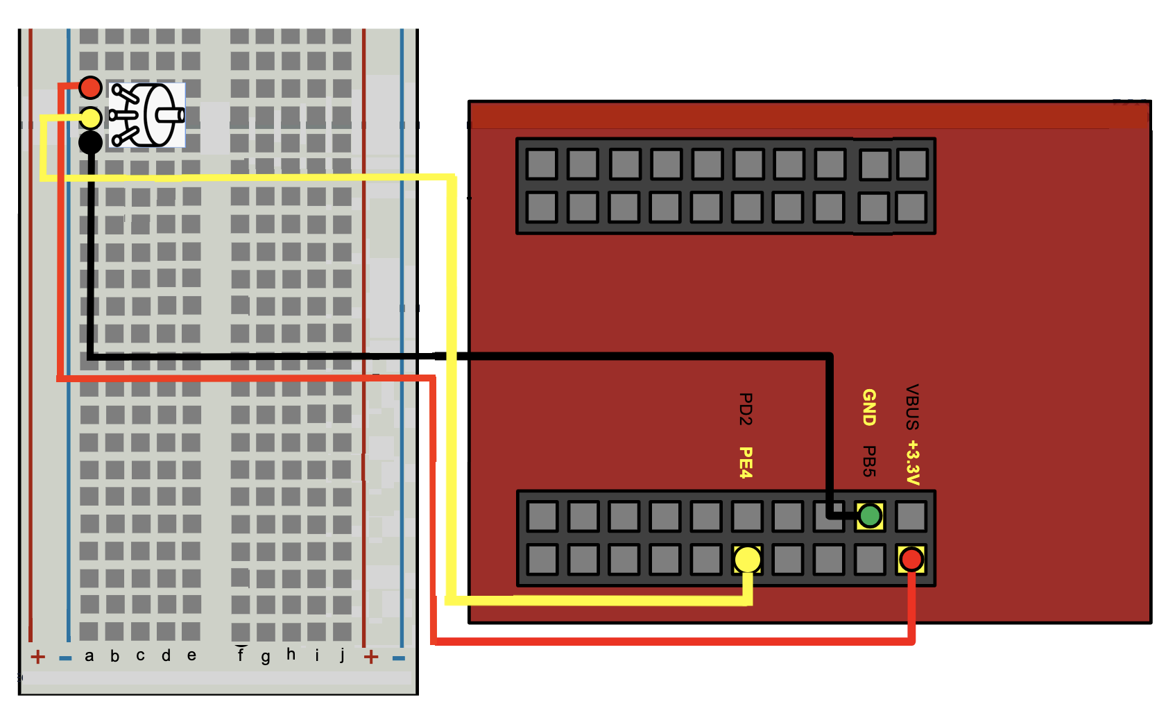
Potentiometer Testing

To make sure the potentiometer does not malfunction, we connect only the potentiometer with the board.

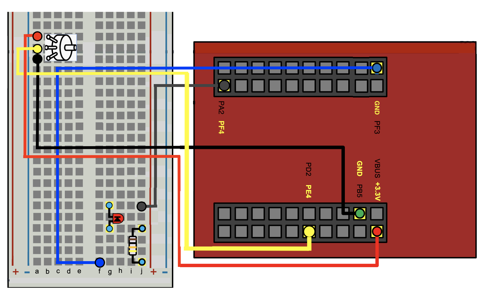
LED Light Testing

To get a more direct observation of the change in frequency, we substitute the Piezo Speaker with a LED light and look at the blinking frequency.

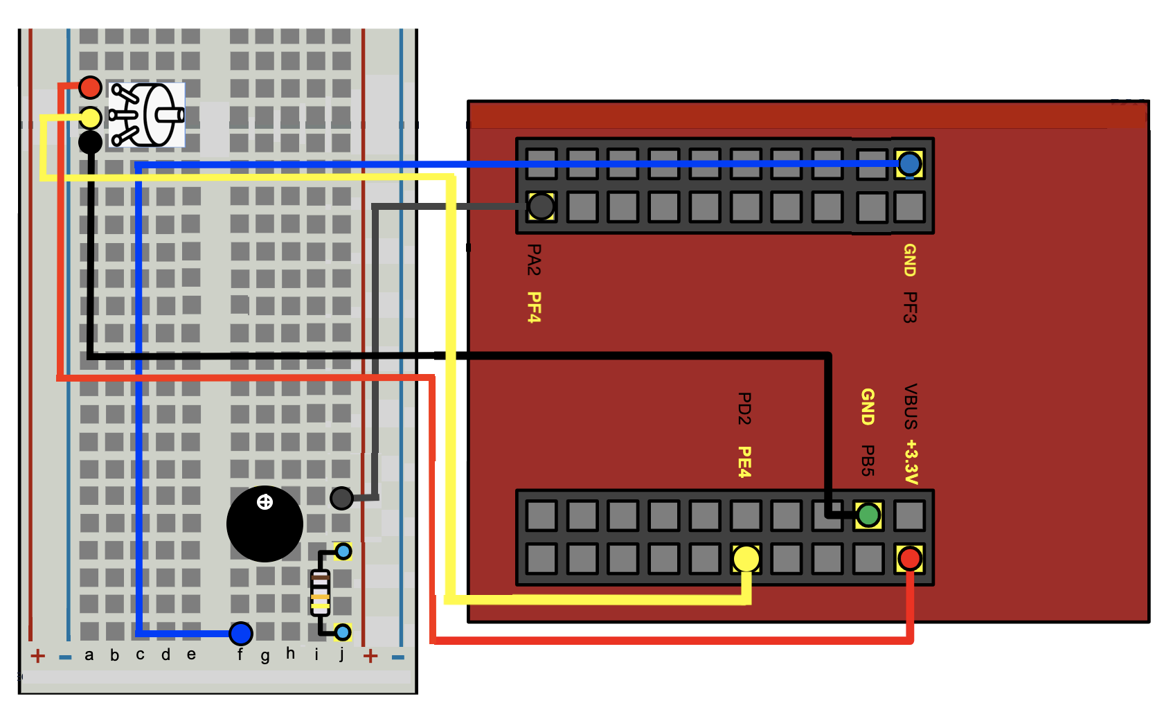
Piezo Speaker Linkage

The final schematic design of our singing buzzer.

Code

helper.h

C/C++
/*
 * helpers.h
 *
 *  Created on: Mar 15, 2018
 *      Author: Chance Tarver
 */

#ifndef HELPERS_H_
#define HELPERS_H_


// Base addresses of each port
#define PortA       0x40004000
#define PortB       0x40058000
#define PortC       0x40006000
#define PortD       0x40007000
#define PortE       0x40024000
#define PortF       0x40025000

//  General-Purpose Input/Output Run Mode Clock Gating Control. Each bit corresponds to a Port.
#define RCGCGPIO    0x400FE608
#define ClocksA     0x01
#define ClocksB     0x02
#define ClocksC     0x04
#define ClocksD     0x08
#define ClocksE     0x10
#define ClocksF     0x20

// Define the bitmask for each pin
#define pin0     0x01
#define pin1     0x02
#define pin2     0x04
#define pin3     0x08
#define pin4     0x10
#define pin5     0x20
#define pin6     0x40

//Other defines for code readability
#define OUTPUT  1
#define INPUT   0
#define INTERRUPT    1
#define NoINTERRUPT  0

// Offsets corresponding to registers we may need to configure
#define GPIODATA    0x3FC   // pg662 : GPIO Data
#define GPIODIR     0x400   // pg663 : GPIO Direction
#define GPIOIS      0x404   // pg664 : GPIO Interrupt Sense
#define GPIOIBE     0x408   // pg665 : GPIO Interrupt Both Edges
#define GPIOIEV     0x40C   // pg666 : GPIO Interrupt Event     -   0: falling edge or Low level is trigger.    1: rising edge or High level is trigger
#define GPIOIM      0x410   // pg667 : GPIO Interrupt Mask      -   0: the pin is masked.                       1: the interrupt is sent to the controller
#define GPIOICR     0x41C   // pg670 : GPIO Interrupt Clear     -   0: no affect                                1: the corresponding interrupt is cleared
#define GPIOAFSEL   0x420   // pg671 : GPIO Alternative Function Select - 0: pin functions as GPIO              1: Function as something else depending on port
#define GPIOPUR     0x510   // pg677 : GPIO Pull-Up Select      -   0: turn off pull up resistor                1: turn on pull up for corresponding pin
#define GPIOPDR     0x514   // pg679 : GPIO Pull-Down Select    -   0: turn off pull down resistor              1: turn on pull down for corresponding pin
#define GPIODEN     0x51C   // pg682 : GPIO Digital Enable      -   0: disable digital functions                1: enable pin's digital functions
#define GPIOLOCK    0x520   // pg684 : GPIO Lock. A write of the value 0x4C4F.434B unlocks the GPIO Commit (GPIOCR) register for write access.
#define GPIOKEY     0x4C4F434B // pg684. Special key for the GPIOLOCK register
#define GPIOCR      0x524   // pg685 : GPIO Commit              -   0: Corresponding GPIOAFSEL, GPIOPUR, GPIOPDR, or GPIODEN bits cannot be written. 1: They can

#define NVIC_EN0_R              (*((volatile unsigned long *)0xE000E100))  // pg142 IRQ 0 to 31 Set Enable Register

#define NVIC_PRI0_R             (*((volatile unsigned long *)0xE000E41C))  // pg152 IRQ 0 to 3 Priority Register
#define NVIC_PRI7_R             (*((volatile unsigned long *)0xE000E41C))  // pg152 IRQ 28 to 31 Priority Register  pg 104 has interrupt assignments. GPIO Port F is Interrupt #30. Bits 23:21

void WaitForInterrupt(void);  // low power mode

void SetupDigitalGPIO(unsigned int port, unsigned int pinMask, int direction,
                        int useInterrupts)
{
    /*Function for setting up a digital GPIO Pin

     This function will do all the register configs for a give port and pin.

     Examples
     -------
     SetupOnDigitalGPIO(PortF, pin3, INPUT, INTERRUPT) // Set up an input with interrupts on PF3.
     SetupOnDigitalGPIO(PortE, pin4, OUTPUT, NoINTERRUPT) // Set up an output with no interrupts on PE4.
     Notes
     -----
     We assume a pullup resistor.
     We also assume an edge based trigger.
     It is best the header with the #defines for each port and pin are included.

     Inputs
     ------
     (*((volatile unsigned long *) port  - Base address of the port being used.
     (*((volatile unsigned long *) pin   - Bit mask of the pin being used
     int direction - Boolean flag for direction of the pin. 1 = Output. 0 = input
     int UseInterrupts - Boolean flag to use interrupts. 1 = use them. 0 = don't
     */

    //Define the generic pointers
    unsigned int volatile *pRCGCGPIO = (unsigned int *) RCGCGPIO;
    unsigned int volatile *pGPIOLOCK = (unsigned int *) (port + GPIOLOCK);
    unsigned int volatile *pGPIOCR = (unsigned int *) (port + GPIOCR);
    unsigned int volatile *pGPIODIR = (unsigned int *) (port + GPIODIR);
    unsigned int volatile *pGPIOAFSEL = (unsigned int *) (port + GPIOAFSEL);
    unsigned int volatile *pGPIOPUR = (unsigned int *) (port + GPIOPUR);
    unsigned int volatile *pGPIODEN = (unsigned int *) (port + GPIODEN);
    unsigned int volatile *pGPIODATA = (unsigned int *) (port + GPIODATA);

    // Define the pointers for interrupt configuration
    unsigned int volatile *pGPIOIS = (unsigned int *) (port + GPIOIS);
    unsigned int volatile *pGPIOIBE = (unsigned int *) (port + GPIOIBE);
    unsigned int volatile *pGPIOIEV = (unsigned int *) (port + GPIOIEV);
    unsigned int volatile *pGPIOIM = (unsigned int *) (port + GPIOIM);
    unsigned int volatile *pGPIOICR = (unsigned int *) (port + GPIOICR);

    // activate the clocks for the port
    int clocks;
    switch ((int) port)
    {
    case PortA:
        clocks = ClocksA;
    case PortB:
        clocks = ClocksB;
    case PortC:
        clocks = ClocksC;
    case PortD:
        clocks = ClocksD;
    case PortE:
        clocks = ClocksE;
    case PortF:
        clocks = ClocksF;
    default:
        clocks = ClocksF; //ERROR. TODO: Add an exception to handle this. Send to Error ISR or something
    }

    *pRCGCGPIO |= clocks;
    while ((*pRCGCGPIO & clocks) == 0)
        ;

    *pGPIOLOCK = GPIOKEY;
    *pGPIOCR |= pinMask;
    if (direction == 0)
    {
        *pGPIODIR &= ~pinMask;
        *pGPIOPUR |= pinMask;
    }
    else if (direction == 1)
    {
        *pGPIODIR |= pinMask;
    }
    else
    {
        *pGPIODIR |= pinMask; // TODO. Addd an exception to handle this.
    }

    *pGPIOAFSEL &= ~pinMask;
    *pGPIODEN |= pinMask;

    if (useInterrupts)
    {
        *pGPIOIS &= ~pinMask;  // Edge-sensitive (default setting)
        *pGPIOIBE &= ~pinMask;  // Not both edges (default setting)
        *pGPIOIEV &= ~pinMask;  // Falling edge event (default setting)
        *pGPIOICR |= pinMask;   // clear flag
        *pGPIOIM |= pinMask;   // enable interrupt. Unmask it
    }
}


void WaitForInterrupt(void)
{
    __asm ("    WFI\n"
            "    BX     LR\n");
}


#endif /* HELPERS_H_ */

main.c

C/C++
#include "helpers.h"
#include "ADC0_registers.h"
#include <math.h>

extern void System_Clock_Init(void);
extern void ADC0_InitSWTriggerSeq3_PE4(void);
extern unsigned int ADC0_Sample_Seq3(void);


double freqency_base = 1000.0;
unsigned int light_status = pin1;

void PortF_ISR(){
    // Registers that we need in the ISR
    unsigned int volatile *pGPIOICR = (unsigned int *) (PortF + GPIOICR);
    unsigned int volatile *pGPIODATA = (unsigned int *) (PortF + GPIODATA);

    *pGPIOICR |= 0x01;
    //    the helper.h has info on the operation of the GPIOICR register.
    //    We are on PF0. You'll need to acknowledge the flag specifically
    //    for pin 0.

    unsigned int light_switch;
    light_status = *pGPIODATA & 0x0f; // get the last four digit of port f data

    // get values for the change
    if (light_status == 0x00) {
        freqency_base = 5500;
        light_switch = pin3;
    }
    else if (light_status == pin3){
        freqency_base = 3000;
        light_switch = pin2;
    }
    else if (light_status == pin2){
        freqency_base = 500;
        light_switch = pin1;
    }
    else if (light_status == pin1){
        light_switch = 0x00;
    }

    // change LED color (change only the last four bits of GPIODATA to light_switch)
    *pGPIODATA = ((*pGPIODATA>>4)<<4)|light_switch;


}

int main(void)
{
    SetupDigitalGPIO(PortF, pin0, INPUT, INTERRUPT);    // SW2
    SetupDigitalGPIO(PortF, pin1, OUTPUT, NoINTERRUPT); // Red LED
    SetupDigitalGPIO(PortF, pin2, OUTPUT, NoINTERRUPT); // Blue LED
    SetupDigitalGPIO(PortF, pin3, OUTPUT, NoINTERRUPT); // Green LED
    SetupDigitalGPIO(PortF, pin4, OUTPUT, NoINTERRUPT); // set up speaker
    unsigned int volatile *pGPIODATA = (unsigned int *) (PortF + GPIODATA);
    *pGPIODATA ^= 0x00;
    // Set priority
    NVIC_PRI7_R = (NVIC_PRI7_R & 0xFF00FFFF) | 0x00A00000; // priority 5

    //Enable
    //   For this register, each bit corresponds to a different interrupt
    //   that can be enabled.
    //   For interrupt 1, you'd need a 1 in bit position 1.
    NVIC_EN0_R |= 0x40000000;
    // buzz with respective frequency
    double sample_voltage;
    int i;

    System_Clock_Init();

    // Done enabling the PLL.
    // Nice function that sets up the ADC for you :)
    ADC0_InitSWTriggerSeq3_PE4();

    // Done with the initialization of the ADC.  Time to do some converting!

    // This is a busy-wait or polling based approach to talking to a typically slow peripheral.  In this case,
    // the peripheral happens to be the ADC we have set up.  0 to 3.3V maps to the sample ranges of
    // 0 to 4095 (2^12 - 1)
    while(1){
        if (light_status == pin1){
            *pGPIODATA &= ~0x10;
        }
        else {
        int sample_ADC0 = ADC0_Sample_Seq3();
        // Let's take the sample we have and turn it into a voltage in the range of 0 to 3.3V
        sample_voltage = (3.3/4095.0) * (double) sample_ADC0;
        *pGPIODATA ^= 0x10;
        for (i=0; i < 757.6*(3.3-sample_voltage)+freqency_base; i++){}
        }
    }
}

tm4c123gh6pm_startup_ccs.c

C/C++
//*****************************************************************************
//
// Startup code for use with TI's Code Composer Studio.
//
// Copyright (c) 2011-2014 Texas Instruments Incorporated.  All rights reserved.
// Software License Agreement
// 
// Software License Agreement
//
// Texas Instruments (TI) is supplying this software for use solely and
// exclusively on TI's microcontroller products. The software is owned by
// TI and/or its suppliers, and is protected under applicable copyright
// laws. You may not combine this software with "viral" open-source
// software in order to form a larger program.
//
// THIS SOFTWARE IS PROVIDED "AS IS" AND WITH ALL FAULTS.
// NO WARRANTIES, WHETHER EXPRESS, IMPLIED OR STATUTORY, INCLUDING, BUT
// NOT LIMITED TO, IMPLIED WARRANTIES OF MERCHANTABILITY AND FITNESS FOR
// A PARTICULAR PURPOSE APPLY TO THIS SOFTWARE. TI SHALL NOT, UNDER ANY
// CIRCUMSTANCES, BE LIABLE FOR SPECIAL, INCIDENTAL, OR CONSEQUENTIAL
// DAMAGES, FOR ANY REASON WHATSOEVER.
//
//*****************************************************************************

#include <stdint.h>

//*****************************************************************************
//
// Forward declaration of the default fault handlers.
//
//*****************************************************************************
void ResetISR(void);
static void NmiSR(void);
static void FaultISR(void);
static void IntDefaultHandler(void);
extern void PortF_ISR(void);
//*****************************************************************************
//
// External declaration for the reset handler that is to be called when the
// processor is started
//
//*****************************************************************************
extern void _c_int00(void);

//*****************************************************************************
//
// Linker variable that marks the top of the stack.
//
//*****************************************************************************
extern uint32_t __STACK_TOP;

//*****************************************************************************
//
// External declarations for the interrupt handlers used by the application.
//
//*****************************************************************************
// To be added by user

//*****************************************************************************
//
// The vector table.  Note that the proper constructs must be placed on this to
// ensure that it ends up at physical address 0x0000.0000 or at the start of
// the program if located at a start address other than 0.
//
//*****************************************************************************
#pragma DATA_SECTION(g_pfnVectors, ".intvecs")
void (* const g_pfnVectors[])(void) =
{
    (void (*)(void))((uint32_t)&__STACK_TOP),
                                            // The initial stack pointer
    ResetISR,                               // The reset handler
    NmiSR,                                  // The NMI handler
    FaultISR,                               // The hard fault handler
    IntDefaultHandler,                      // The MPU fault handler
    IntDefaultHandler,                      // The bus fault handler
    IntDefaultHandler,                      // The usage fault handler
    0,                                      // Reserved
    0,                                      // Reserved
    0,                                      // Reserved
    0,                                      // Reserved
    IntDefaultHandler,                      // SVCall handler
    IntDefaultHandler,                      // Debug monitor handler
    0,                                      // Reserved
    IntDefaultHandler,                      // The PendSV handler
    IntDefaultHandler,                      // The SysTick handler
    IntDefaultHandler,                      // GPIO Port A
    IntDefaultHandler,                      // GPIO Port B
    IntDefaultHandler,                      // GPIO Port C
    IntDefaultHandler,                      // GPIO Port D
    IntDefaultHandler,                      // GPIO Port E
    IntDefaultHandler,                      // UART0 Rx and Tx
    IntDefaultHandler,                      // UART1 Rx and Tx
    IntDefaultHandler,                      // SSI0 Rx and Tx
    IntDefaultHandler,                      // I2C0 Master and Slave
    IntDefaultHandler,                      // PWM Fault
    IntDefaultHandler,                      // PWM Generator 0
    IntDefaultHandler,                      // PWM Generator 1
    IntDefaultHandler,                      // PWM Generator 2
    IntDefaultHandler,                      // Quadrature Encoder 0
    IntDefaultHandler,                      // ADC Sequence 0
    IntDefaultHandler,                      // ADC Sequence 1
    IntDefaultHandler,                      // ADC Sequence 2
    IntDefaultHandler,                      // ADC Sequence 3
    IntDefaultHandler,                      // Watchdog timer
    IntDefaultHandler,                      // Timer 0 subtimer A
    IntDefaultHandler,                      // Timer 0 subtimer B
    IntDefaultHandler,                      // Timer 1 subtimer A
    IntDefaultHandler,                      // Timer 1 subtimer B
    IntDefaultHandler,                      // Timer 2 subtimer A
    IntDefaultHandler,                      // Timer 2 subtimer B
    IntDefaultHandler,                      // Analog Comparator 0
    IntDefaultHandler,                      // Analog Comparator 1
    IntDefaultHandler,                      // Analog Comparator 2
    IntDefaultHandler,                      // System Control (PLL, OSC, BO)
    IntDefaultHandler,                      // FLASH Control
    PortF_ISR,                              // GPIO Port F
    IntDefaultHandler,                      // GPIO Port G
    IntDefaultHandler,                      // GPIO Port H
    IntDefaultHandler,                      // UART2 Rx and Tx
    IntDefaultHandler,                      // SSI1 Rx and Tx
    IntDefaultHandler,                      // Timer 3 subtimer A
    IntDefaultHandler,                      // Timer 3 subtimer B
    IntDefaultHandler,                      // I2C1 Master and Slave
    IntDefaultHandler,                      // Quadrature Encoder 1
    IntDefaultHandler,                      // CAN0
    IntDefaultHandler,                      // CAN1
    0,                                      // Reserved
    0,                                      // Reserved
    IntDefaultHandler,                      // Hibernate
    IntDefaultHandler,                      // USB0
    IntDefaultHandler,                      // PWM Generator 3
    IntDefaultHandler,                      // uDMA Software Transfer
    IntDefaultHandler,                      // uDMA Error
    IntDefaultHandler,                      // ADC1 Sequence 0
    IntDefaultHandler,                      // ADC1 Sequence 1
    IntDefaultHandler,                      // ADC1 Sequence 2
    IntDefaultHandler,                      // ADC1 Sequence 3
    0,                                      // Reserved
    0,                                      // Reserved
    IntDefaultHandler,                      // GPIO Port J
    IntDefaultHandler,                      // GPIO Port K
    IntDefaultHandler,                      // GPIO Port L
    IntDefaultHandler,                      // SSI2 Rx and Tx
    IntDefaultHandler,                      // SSI3 Rx and Tx
    IntDefaultHandler,                      // UART3 Rx and Tx
    IntDefaultHandler,                      // UART4 Rx and Tx
    IntDefaultHandler,                      // UART5 Rx and Tx
    IntDefaultHandler,                      // UART6 Rx and Tx
    IntDefaultHandler,                      // UART7 Rx and Tx
    0,                                      // Reserved
    0,                                      // Reserved
    0,                                      // Reserved
    0,                                      // Reserved
    IntDefaultHandler,                      // I2C2 Master and Slave
    IntDefaultHandler,                      // I2C3 Master and Slave
    IntDefaultHandler,                      // Timer 4 subtimer A
    IntDefaultHandler,                      // Timer 4 subtimer B
    0,                                      // Reserved
    0,                                      // Reserved
    0,                                      // Reserved
    0,                                      // Reserved
    0,                                      // Reserved
    0,                                      // Reserved
    0,                                      // Reserved
    0,                                      // Reserved
    0,                                      // Reserved
    0,                                      // Reserved
    0,                                      // Reserved
    0,                                      // Reserved
    0,                                      // Reserved
    0,                                      // Reserved
    0,                                      // Reserved
    0,                                      // Reserved
    0,                                      // Reserved
    0,                                      // Reserved
    0,                                      // Reserved
    0,                                      // Reserved
    IntDefaultHandler,                      // Timer 5 subtimer A
    IntDefaultHandler,                      // Timer 5 subtimer B
    IntDefaultHandler,                      // Wide Timer 0 subtimer A
    IntDefaultHandler,                      // Wide Timer 0 subtimer B
    IntDefaultHandler,                      // Wide Timer 1 subtimer A
    IntDefaultHandler,                      // Wide Timer 1 subtimer B
    IntDefaultHandler,                      // Wide Timer 2 subtimer A
    IntDefaultHandler,                      // Wide Timer 2 subtimer B
    IntDefaultHandler,                      // Wide Timer 3 subtimer A
    IntDefaultHandler,                      // Wide Timer 3 subtimer B
    IntDefaultHandler,                      // Wide Timer 4 subtimer A
    IntDefaultHandler,                      // Wide Timer 4 subtimer B
    IntDefaultHandler,                      // Wide Timer 5 subtimer A
    IntDefaultHandler,                      // Wide Timer 5 subtimer B
    IntDefaultHandler,                      // FPU
    0,                                      // Reserved
    0,                                      // Reserved
    IntDefaultHandler,                      // I2C4 Master and Slave
    IntDefaultHandler,                      // I2C5 Master and Slave
    IntDefaultHandler,                      // GPIO Port M
    IntDefaultHandler,                      // GPIO Port N
    IntDefaultHandler,                      // Quadrature Encoder 2
    0,                                      // Reserved
    0,                                      // Reserved
    IntDefaultHandler,                      // GPIO Port P (Summary or P0)
    IntDefaultHandler,                      // GPIO Port P1
    IntDefaultHandler,                      // GPIO Port P2
    IntDefaultHandler,                      // GPIO Port P3
    IntDefaultHandler,                      // GPIO Port P4
    IntDefaultHandler,                      // GPIO Port P5
    IntDefaultHandler,                      // GPIO Port P6
    IntDefaultHandler,                      // GPIO Port P7
    IntDefaultHandler,                      // GPIO Port Q (Summary or Q0)
    IntDefaultHandler,                      // GPIO Port Q1
    IntDefaultHandler,                      // GPIO Port Q2
    IntDefaultHandler,                      // GPIO Port Q3
    IntDefaultHandler,                      // GPIO Port Q4
    IntDefaultHandler,                      // GPIO Port Q5
    IntDefaultHandler,                      // GPIO Port Q6
    IntDefaultHandler,                      // GPIO Port Q7
    IntDefaultHandler,                      // GPIO Port R
    IntDefaultHandler,                      // GPIO Port S
    IntDefaultHandler,                      // PWM 1 Generator 0
    IntDefaultHandler,                      // PWM 1 Generator 1
    IntDefaultHandler,                      // PWM 1 Generator 2
    IntDefaultHandler,                      // PWM 1 Generator 3
    IntDefaultHandler                       // PWM 1 Fault
};

//*****************************************************************************
//
// This is the code that gets called when the processor first starts execution
// following a reset event.  Only the absolutely necessary set is performed,
// after which the application supplied entry() routine is called.  Any fancy
// actions (such as making decisions based on the reset cause register, and
// resetting the bits in that register) are left solely in the hands of the
// application.
//
//*****************************************************************************
void
ResetISR(void)
{
    //
    // Jump to the CCS C initialization routine.  This will enable the
    // floating-point unit as well, so that does not need to be done here.
    //
    __asm("    .global _c_int00\n"
          "    b.w     _c_int00");
}

//*****************************************************************************
//
// This is the code that gets called when the processor receives a NMI.  This
// simply enters an infinite loop, preserving the system state for examination
// by a debugger.
//
//*****************************************************************************
static void
NmiSR(void)
{
    //
    // Enter an infinite loop.
    //
    while(1)
    {
    }
}

//*****************************************************************************
//
// This is the code that gets called when the processor receives a fault
// interrupt.  This simply enters an infinite loop, preserving the system state
// for examination by a debugger.
//
//*****************************************************************************
static void
FaultISR(void)
{
    //
    // Enter an infinite loop.
    //
    while(1)
    {
    }
}

//*****************************************************************************
//
// This is the code that gets called when the processor receives an unexpected
// interrupt.  This simply enters an infinite loop, preserving the system state
// for examination by a debugger.
//
//*****************************************************************************
static void
IntDefaultHandler(void)
{
    //
    // Go into an infinite loop.
    //
    while(1)
    {
    }
}

potentiometer_test

C/C++
To test linearity of potentiometer
#include "ADC0_registers.h"

extern void System_Clock_Init(void);
extern void ADC0_InitSWTriggerSeq3_PE4(void);
extern unsigned int ADC0_Sample_Seq3(void);

int main(void){
    float sample_voltage;
    System_Clock_Init();
    // Done enabling the PLL.
    ADC0_InitSWTriggerSeq3_PE4();
    // Done with the initialization of the ADC.

    while(1){
        int sample_ADC0 = ADC0_Sample_Seq3();
        // Let's take the sample we have and turn it into a voltage in the range of 0 to 3.3V
        sample_voltage = (3.3/4095.0) * (double) sample_ADC0;
    }
}

Credits

James Li
1 project • 1 follower
Jiaqi (Lucia) Lu
1 project • 1 follower
Yaning Hu
1 project • 1 follower
Kaichun Luo
1 project • 1 follower
Peter_Jia
1 project • 1 follower
Thanks to Yueqian Li (yl176), Kaichun Luo (kl68), Jiaqi Lu (jl208), Yaning Hu(yh74), and Guancong Jia(gj6).

Comments